
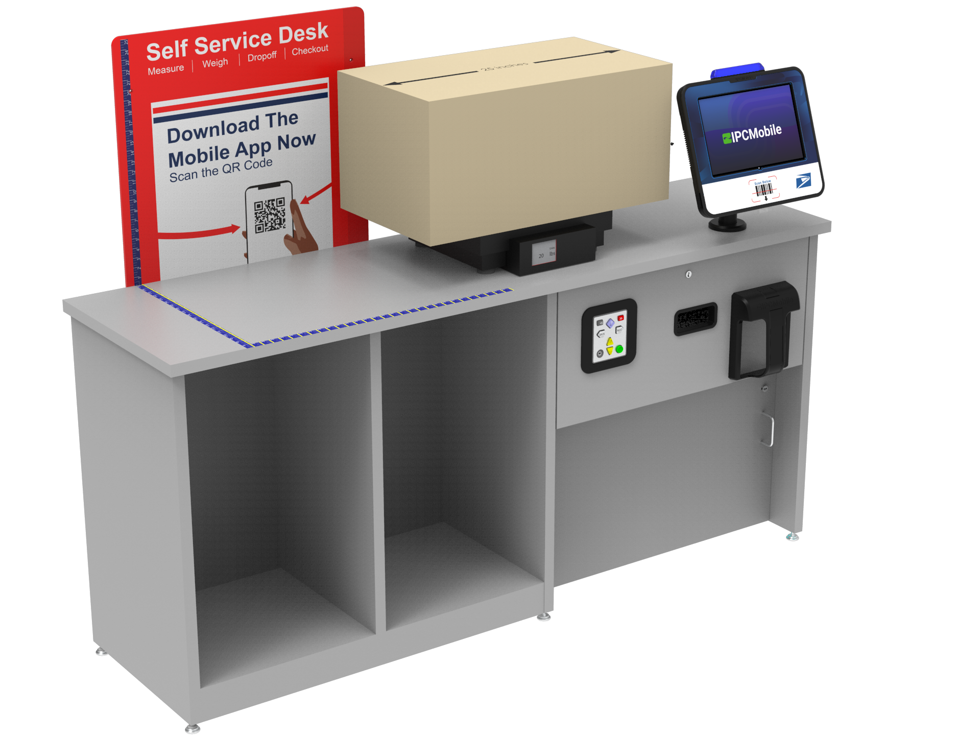
RDS Setup Guide - Extended Desk
To RDS Troubleshooting Guide 🔎 ⏭️
Table of Contents 📝
-
- Step 1 | Install OMNI + Pole Mount
- Step 2 | Route OMNI Harness
- Step 3 | Install Sub-System
- Step 4 | Route Drawer Harness
- Step 5 | Connect Omni Harness to Sub-System
- Step 6 | Install Label Catch onto Drawer
- Step 7 | Install Printers
- Step 8 | Connect ADA Panel
- Step 9 | Connect System to Power
- Step 10 | Power ON Tablet
- Step 11 | Install Tablet into OMNI
- Step 12 | Install Ethernet Cable
- Step 13 | RDS Application Initialization
- Step 14 | Run Test Transaction Using Test Barcodes
- Step 15 | Anchor Desk
- FINAL STEPS
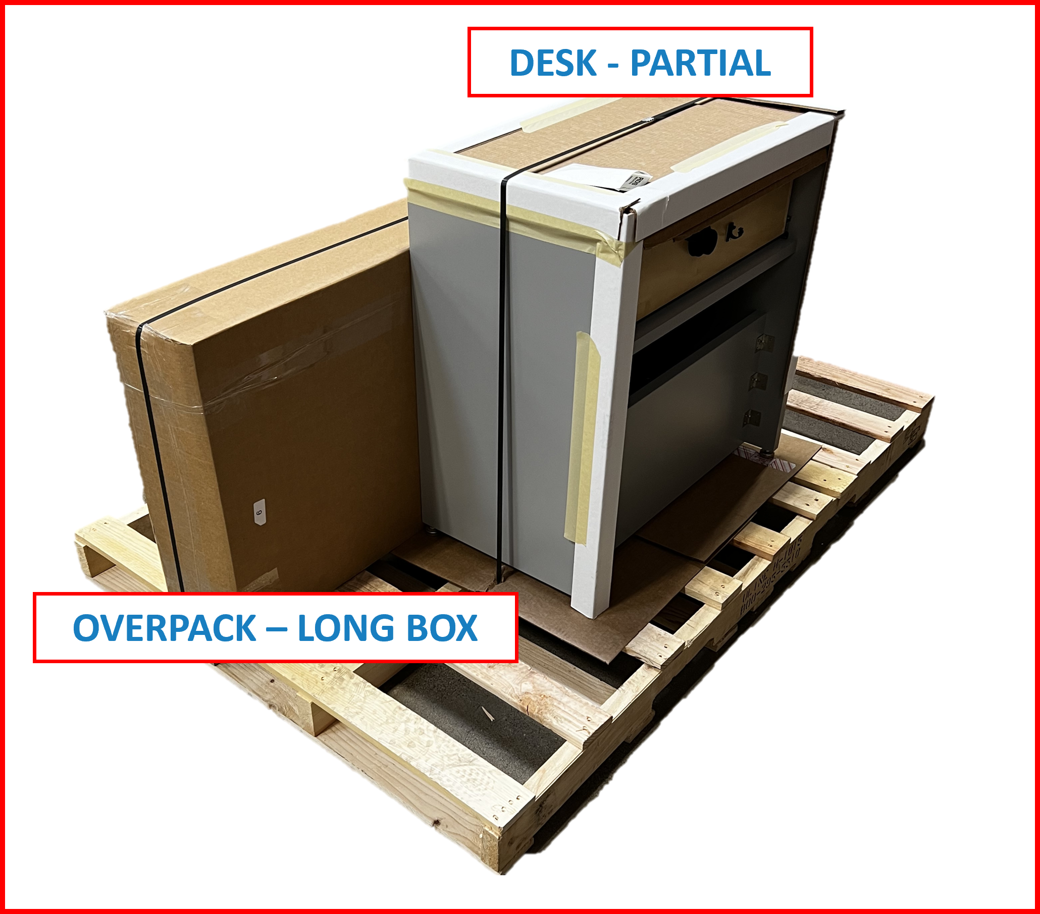
Unboxing Desk Pack 📦
RDS Extended Desk should arrive as shown:
Palletized Package
P/N: RDS-DESK-E-1
Figure EA.1

Removing any shrink wrap, strapping and outer box liner will reveal the packaged contents underneath:
Overpacks
Figure EA.2
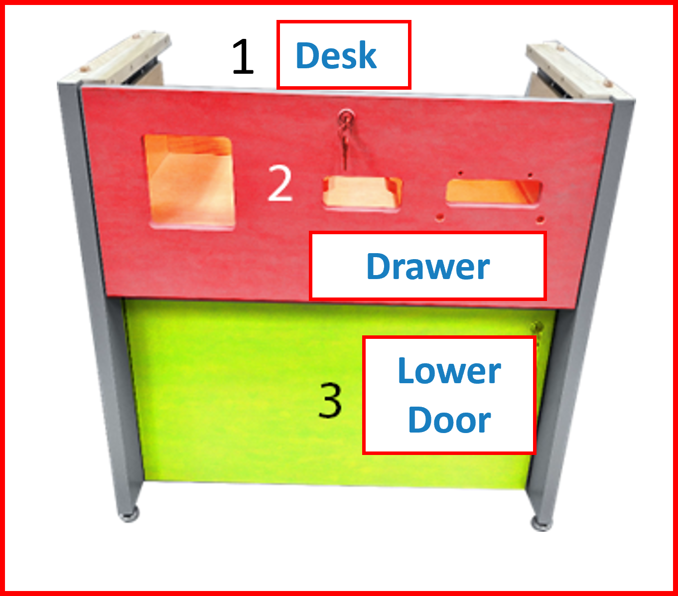
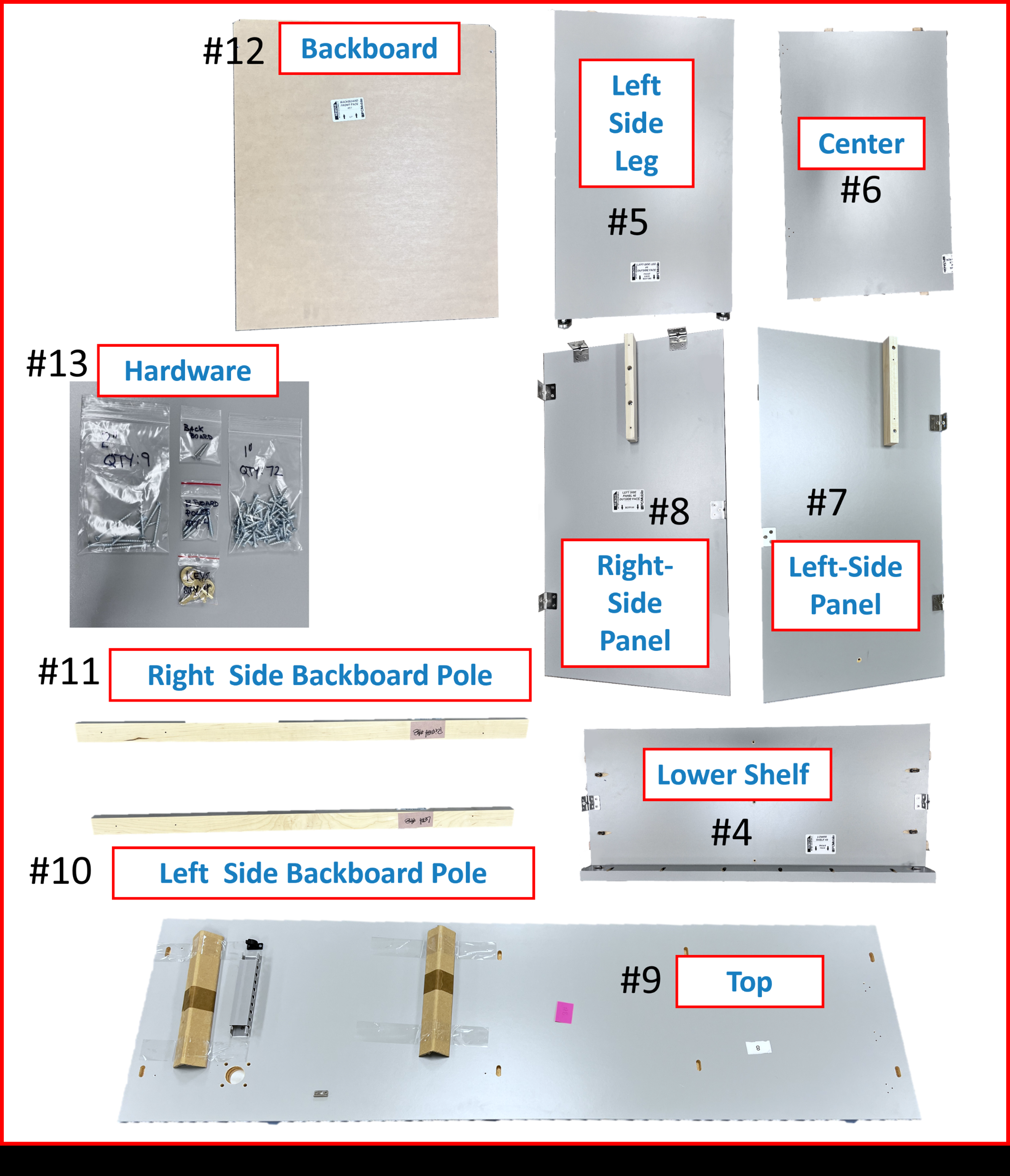
Contents Checklist - DESK PACK - EXTENDED ✅:
-
RDS DESK - PARTIAL- ☑️
Desk#1 --> (Pre-assembled w/Drawer#2 ,Lower Service Door#3 , andLocks)
- ☑️
-
OVERPACK - LONG BOX- ☑️
Lower Shelf#4 - ☑️
Left Side Leg#5 - ☑️
Center#6 - ☑️
Left-Side Panel#7 - ☑️
Right-Side Panel#8 - ☑️
TOP#9 --> (longest component) - ☑️
Left Side Backboard Pole#10 - ☑️
Right Side Backboard Pole#11 - ☑️
Backboard#12 - ☑️
Hardware#13
- ☑️
Unboxing DESK - PARTIAL
- Remove DESK from pallete.
Figure EA.3
ℹ️ NOTE
KEYSfor the Drawer and Service Door locks ofDESKare located inBOX 7and will be needed for the future assembly steps.
Unboxing OVERPACK - LONG BOX
- Remove contents from packaging:
Figure EA.4
Desk Assembly 🪛
Tools Required to Assemble Extended Desk
- Drill/Driver with torque clutch.
- #2 Phillips Driver Bit
- #2 Square Driver Bit
- 2” Drill Driver Extension*
- Approximately 5/8” Thick Object. Something sturdy. A book, box, cardboard, etc...
*Can use 2 Drill Drivers equipped with 2-3” long Driver bits: Items 2 & 3. There will be a need to change bits frequently.
ADVISORY
⚠️ WARNING
TWO OR MORE PEOPLE ARE REQUIRED WHILE MOVING, SHIFTING, OR LIFTING THE EXTENDED DESK AT ALL TIMES WHEN ASSEMBLING THE EXTENDED DESK.
Orientation References Used in This Document:
Figure EA.5
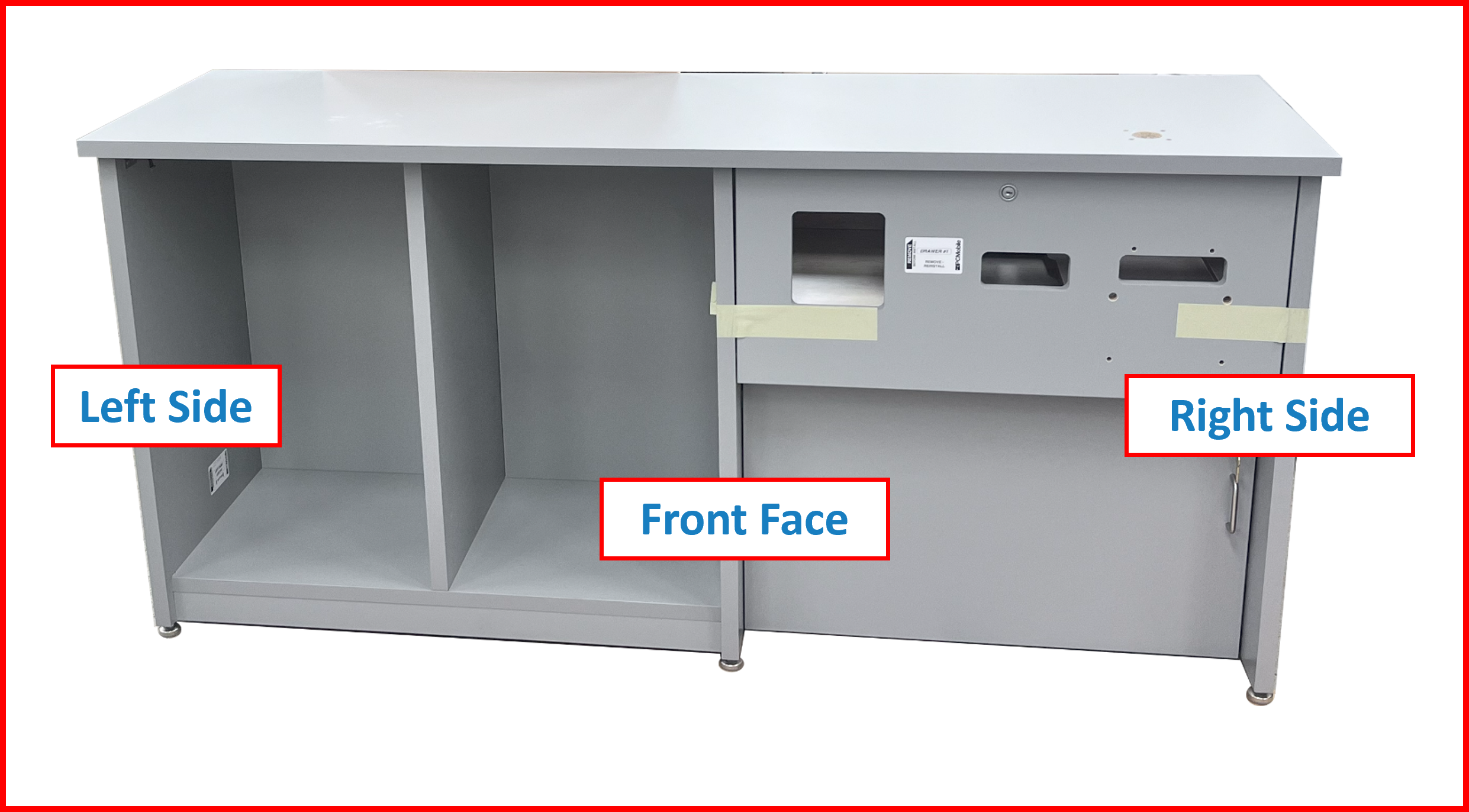
❗ IMPORTANT
PLEASE NOTE ASSEMBLY WILL BE DONE WITH THE FRONT-FACE DOWN. ORIENTATION IS BASED ON THE ORIENTATION OF THE EXTENDED DESK WHEN IT IS STANDING AND YOU ARE LOOKING AT THE FRONT OF THE DESK. THE LEFT SIDE WILL BE ON THE RIGHT SIDE WHEN ASSEMBLING.
Things to do Before Assembling the Extended Desk
❗ IMPORTANT
BEFORE TURNING THE DESK ON ITS FACE, THE FOLLOWING STEPS MUST BE PERFORMED.
Drawer Removal
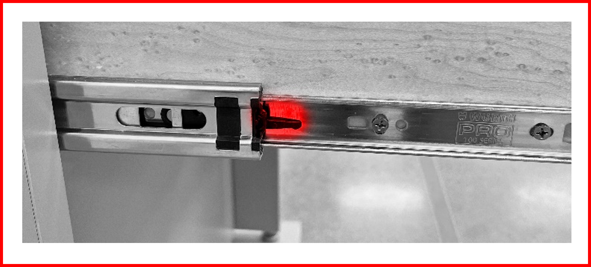
Remove the Drawer #2. The Extended Desk will be assembled front face down. It will be best to remove the drawer to prevent damage to the drawer.
- Pull the drawer out as far as possible.
- On the left side of the drawer, locate the black lever in the slide. Place a finger below it and keep your finger there.
Figure EA.6
- On the right side of the drawer, locate the black lever in the slide. Place a finger above it.
Figure EA.7
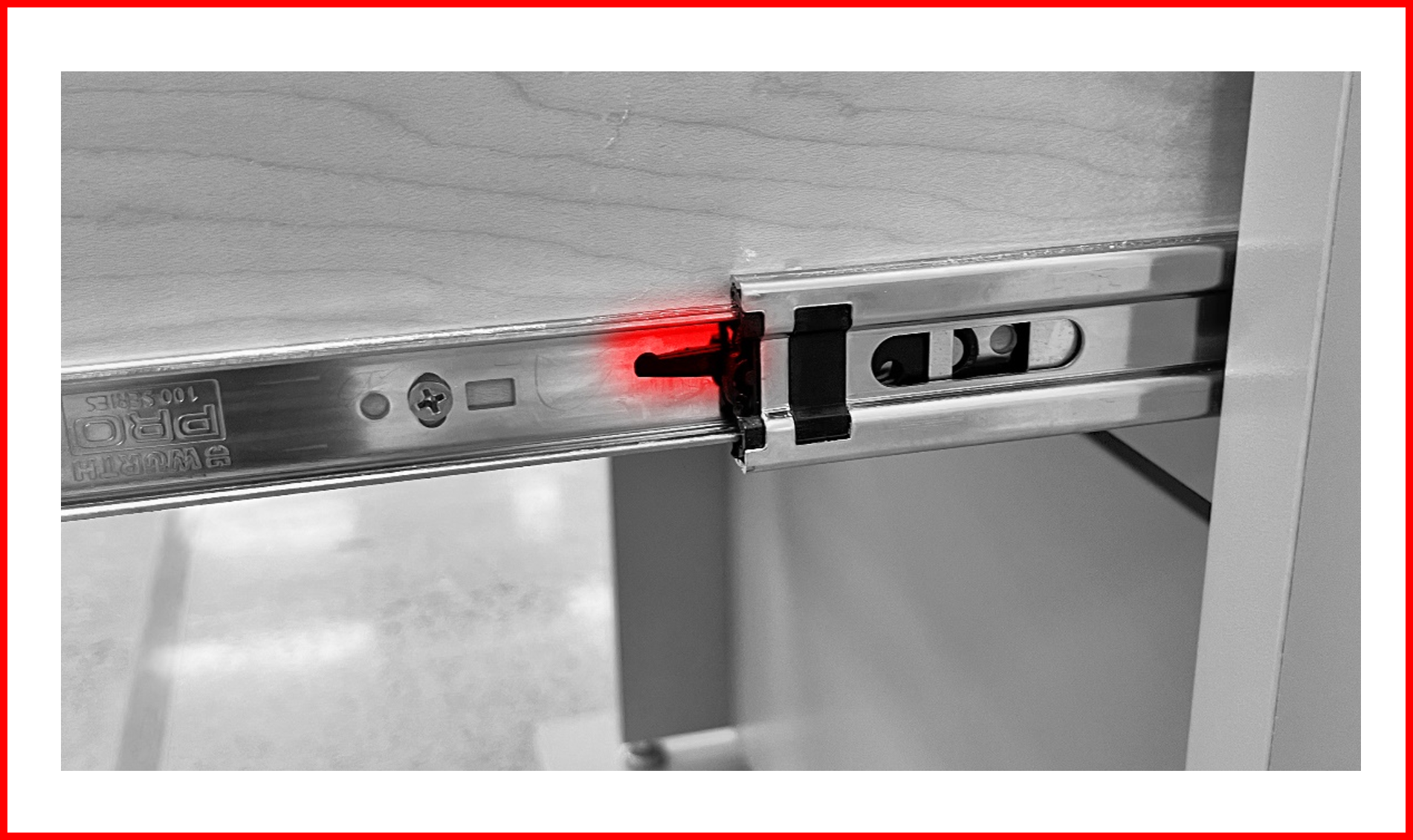
- Pull the left lever up and push the right lever down at the same time and pull the drawer out completely.
- During this process, ensure there is room to back up as removing the drawer may require a step or two backwards.
- At this point, ensure the lower door is locked as in future steps you will be rotating the desk portion face down.
Lock The Lower Door
Lock the Lower Door #3. Again, the Extended Desk will be assembled face down and locking this door will prevent damage to the door.
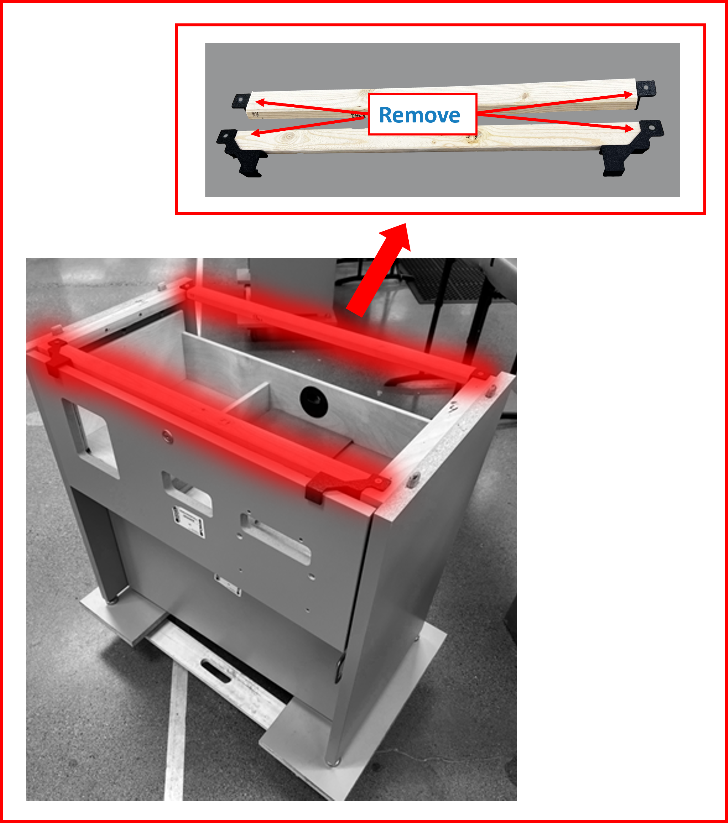
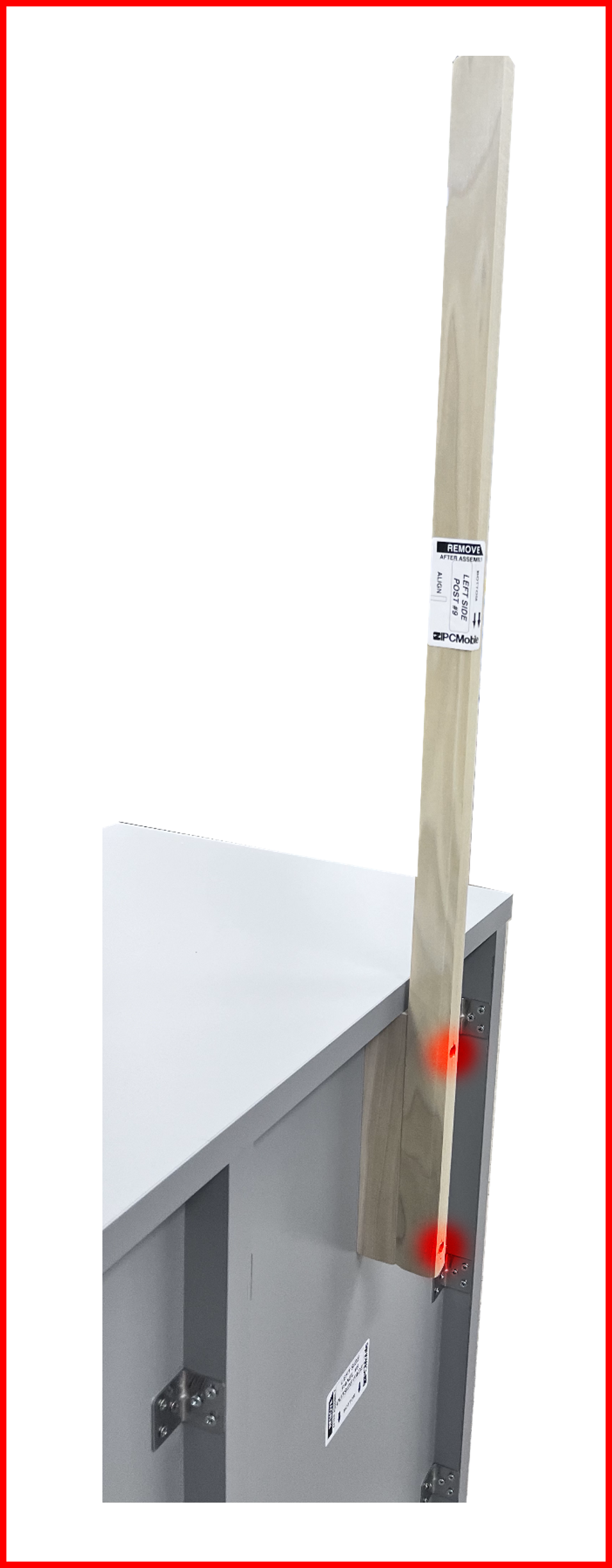
Remove Shipping Braces
Remove shipping braces. Remove the plastic end pieces and set aside, you can use them as support blocks later in the assembly process.
Figure EA.8
Assembling the Extension
Assembly Overview:
The Extended Desk components and assembly sequence are numerically labeled roughly in the order of operation. Please remove all labels after each assembly step is complete.
Figure EA.9
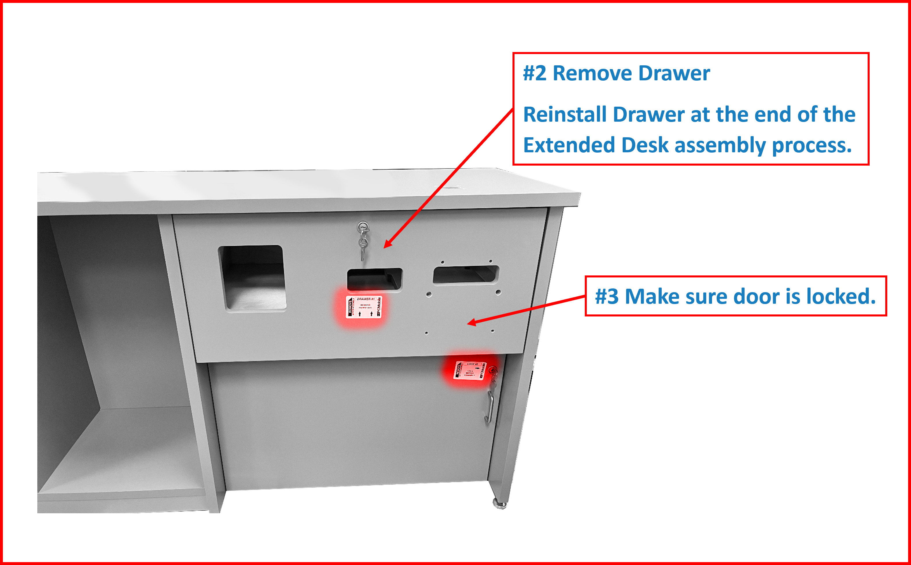
Figure EA.10
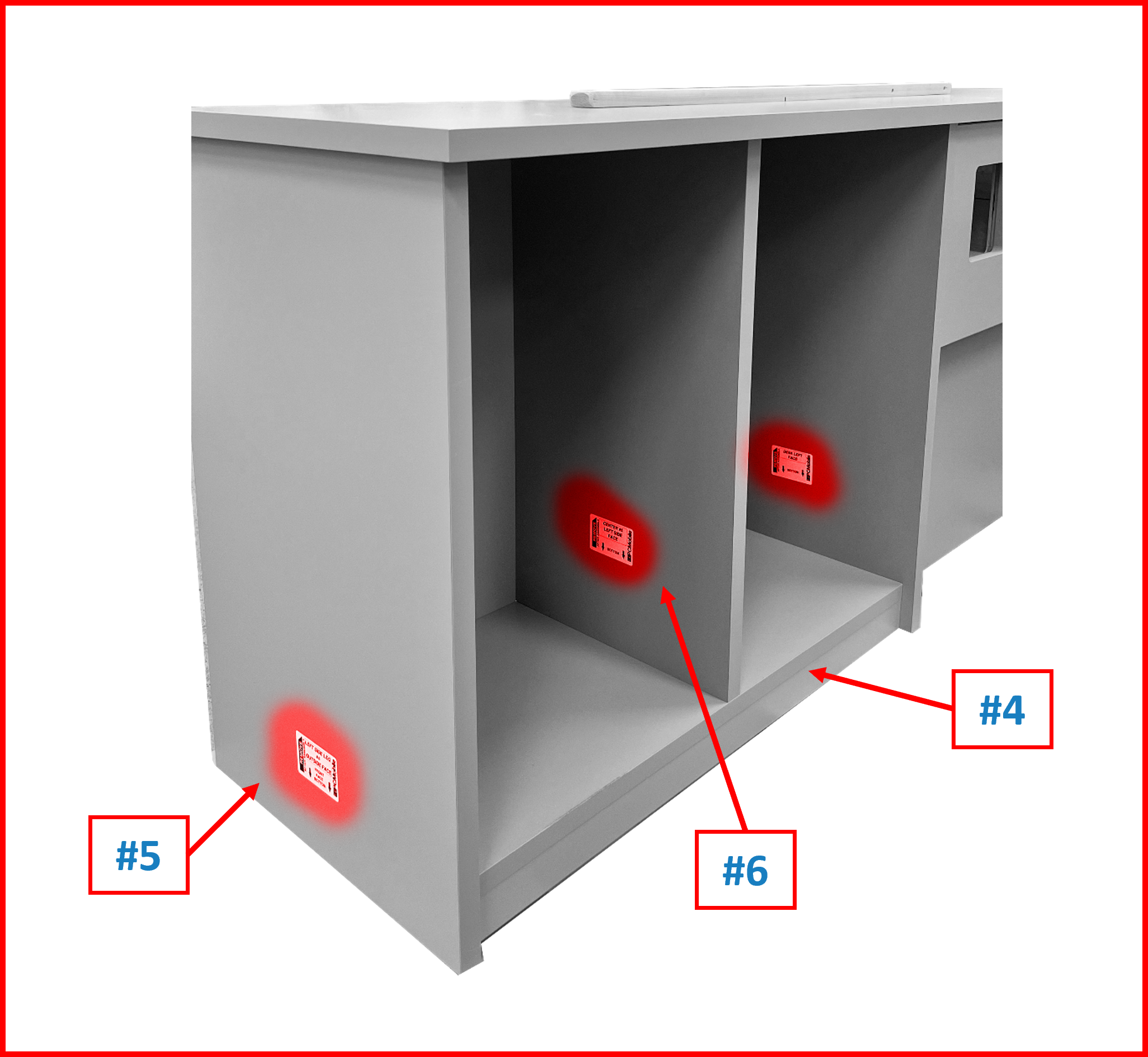
Figure EA.11
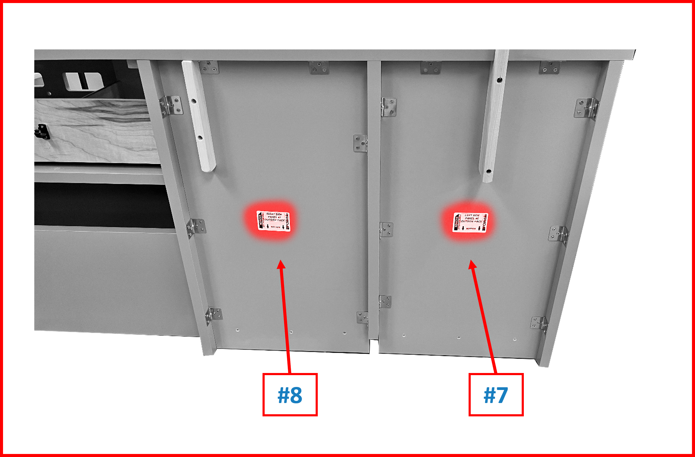
Figure EA.12
Assembling the Lower Shelf
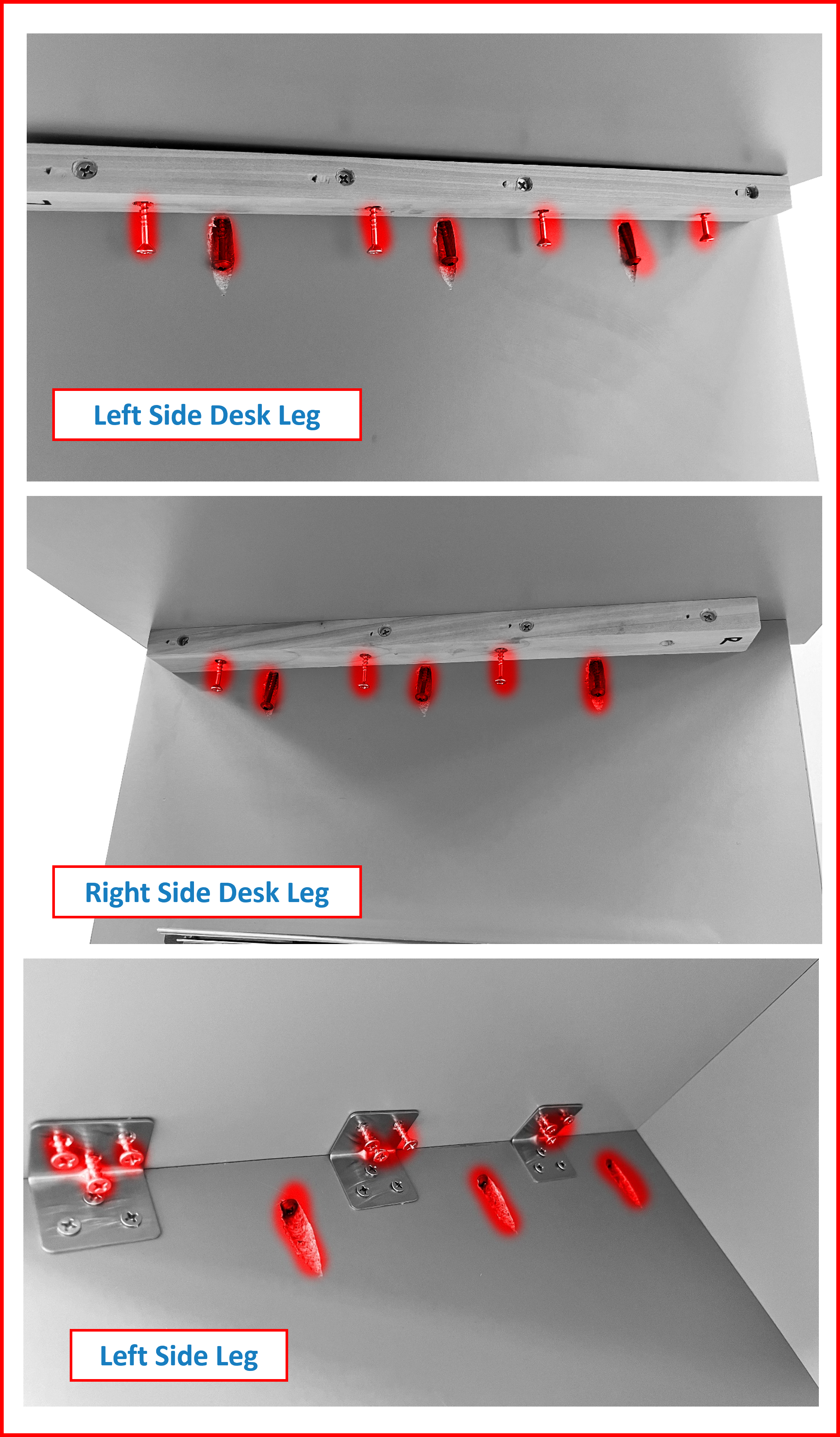
- On a protected surface, place the Lower Shelf #4 and the Left Leg #5. Ensure the highlighted features are oriented as shown.
Figure EA.13
- Place the Left Side Leg on its front edge. The adjustable feet should be facing the same side as the short L and the alignment slots will be facing the lower shelf as shown. Align the alignment slots with the alignment pins then push together. You will need to lift the lower shelf to align. Pro Tip: Use the shipping braces under the front face of the Lower Shelf to easily align the pins in the Lower Shelf with the slots in the Left Side Leg.
Figure EA.14
- Tighten the three pre-attached pocket hole screws using a #2 square bit. Use the median torque setting (7 or 8) on a drill driver as to not strip the wood screw holes, while the screws are still tight. Approximately 7-10nM or 5-7 ft/lbs. torque. Leave the torque setting alone, if using only one drill/driver, or copy settings if using two for the remaining steps.
Figure EA.15
- Place 3 – 1” wood screws each (total 9 screws) into the angle brackets and tighten using a #2 Phillips bit. Use the same median torque setting (7 or 8) on a drill driver as to not strip the wood screw holes, yet screws are still tight. Approximately 7-10nM or 5-7 ft/lbs. torque. Keep this setting.
Figure EA.16
- Leave assembly on its front face until directed to in the step to install the Top #9.
Assembling the Center
- Align the alignment slots in the lower shelf with the alignment pins in the Center #6 as shown. Ensure that the pre-drilled pilot holes are up as shown. Push together. Pro Tip: Use the shipping braces to help prop up the other end of the Center to aid in tightening the three wood screws located in the bottom of the Lower Shelf.
Figure EA.17
- Place 3 – 2” wood screws into the countersunk holes and tighten.
Figure EA.18
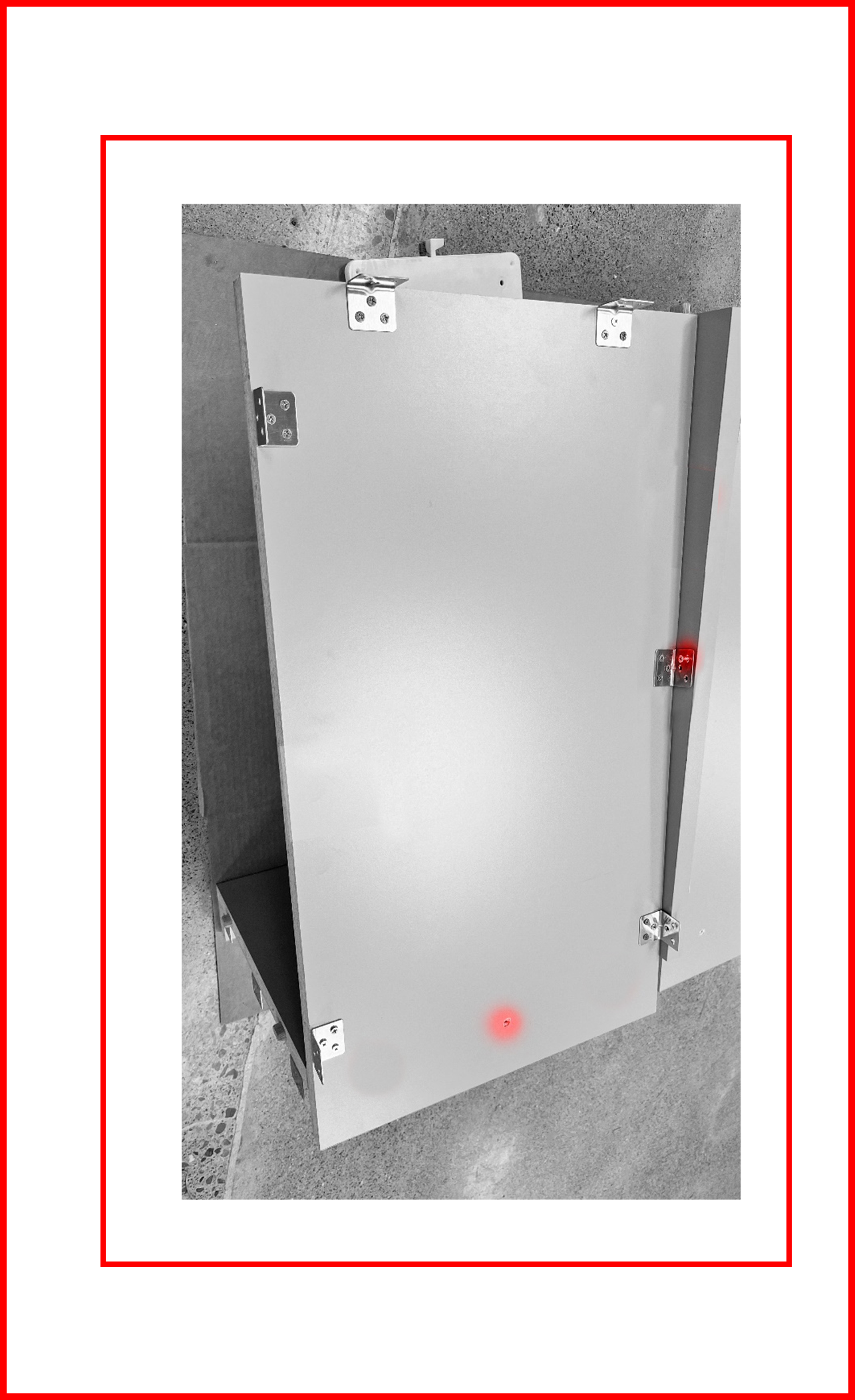
Assembling the Left Panel
- Place the bottom of the Left Side Panel #7 towards the bottom of the assembly and rest the bottom on the lower shelf. Place two 1” screws into the brackets on the top end of the Left Panel by hand. Screws do not have to be fully tightened. The screws only need to hold the panel in place so the remaining screws can be fully tightened.
Figure EA.19
-
Place 3 – 2” screws through the three countersunk holes and tighten.
-
Place remaining screws through the brackets and tighten.
Figure EA.20
Assembling the Right Panel
- Repeat step 1 from the Left panel assembly. Only one screw can be used to hold the Right Panel #8 in place.
Figure EA.21
- Place 3 – 2” countersink screws into the three countersunk holes and tighten.
- Fill remaining brackets with 1” screws and tighten.
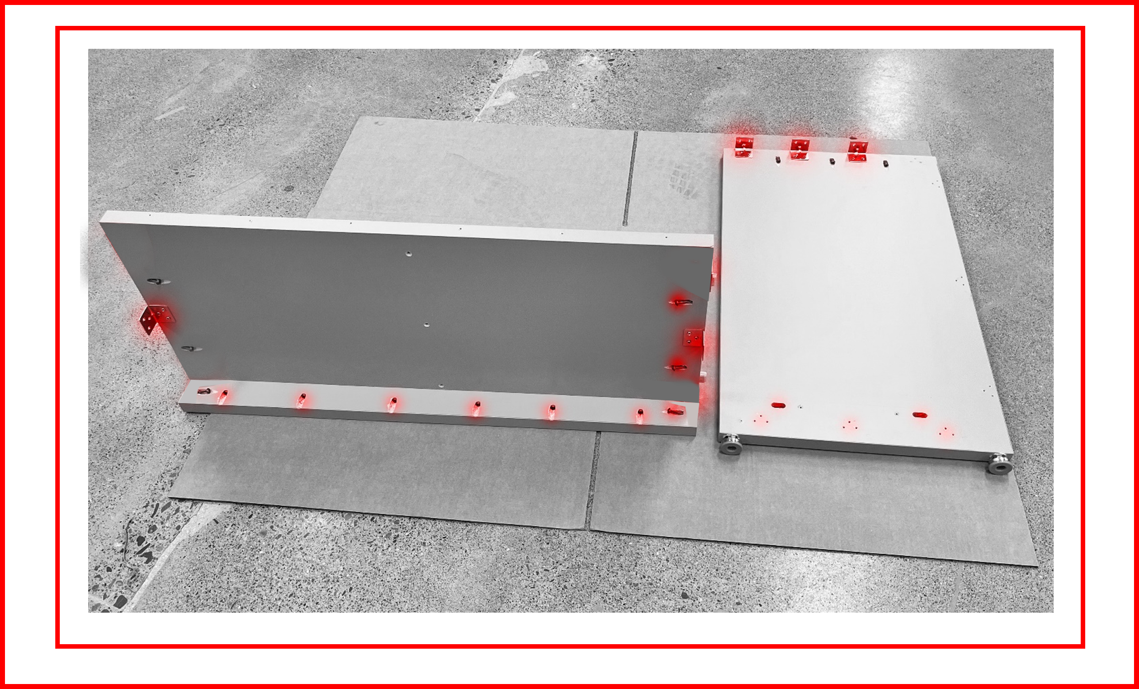
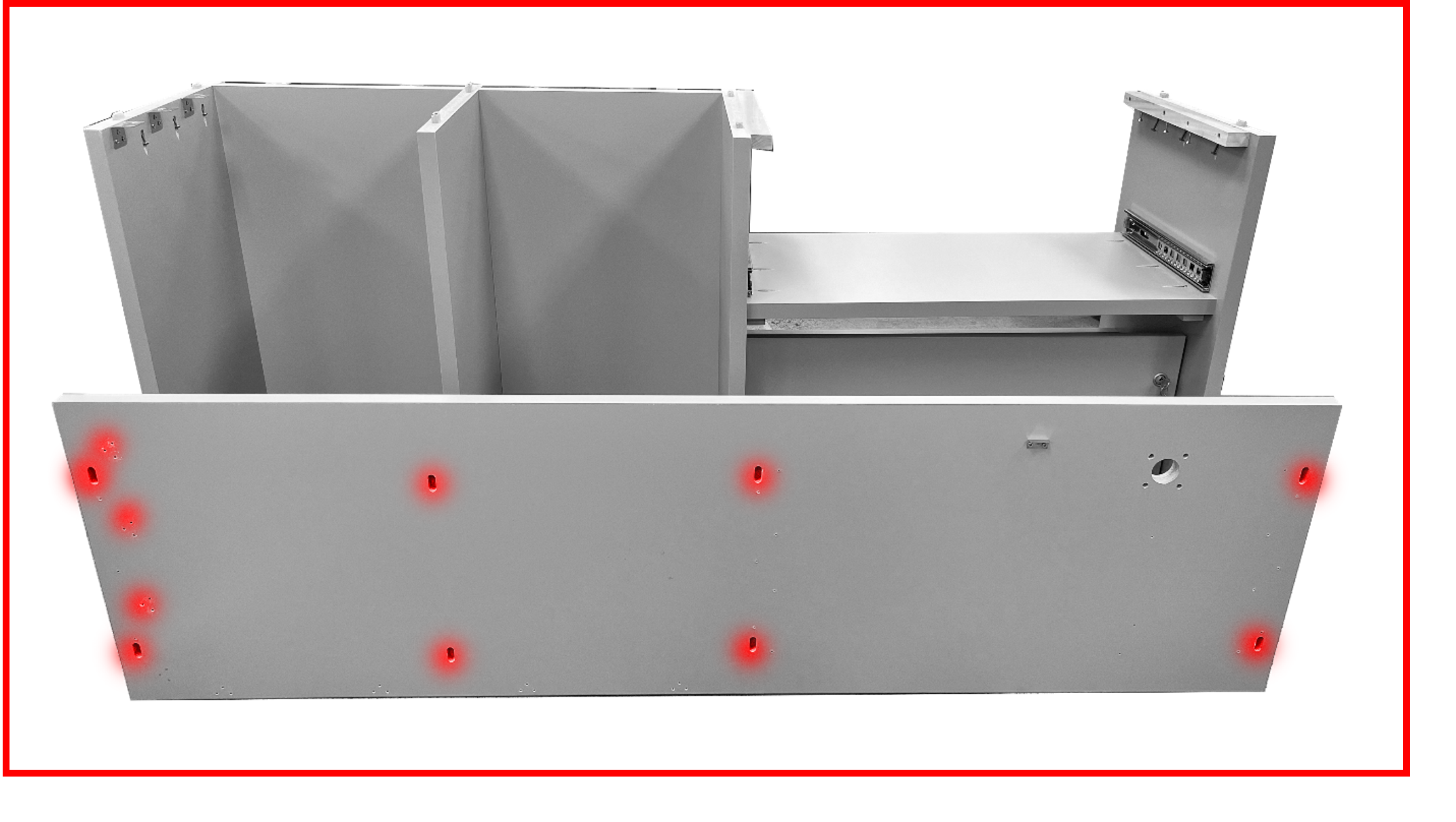
Assembling the Extension to the Desk
- Keep the Extension, front-face down. Place the Desk front-face down next to the Extension so that the left side of the Desk, #1, is near the right side of the Extension. The correct orientation can be identified easily as the adjustable feet will be on the same side and the alignment slots will mate with the alignment pins.
⚠️ WARNING
THIS IS A TEAM LIFT OPERATION!
Figure EA.22
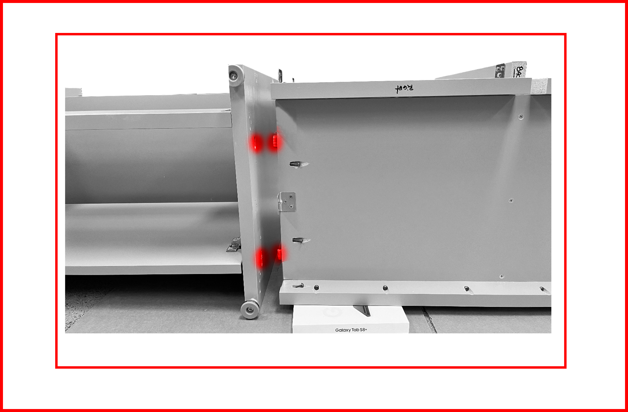
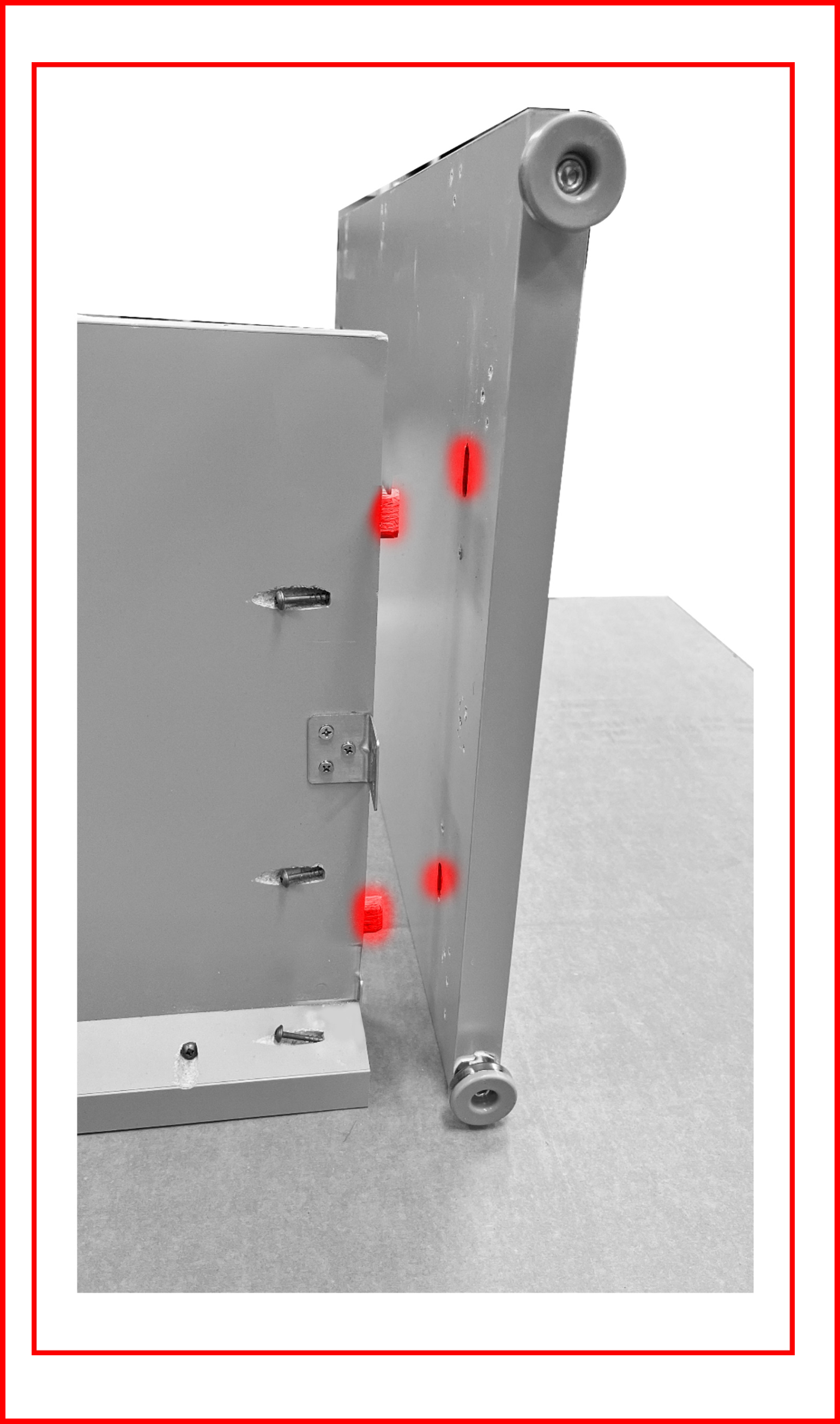
- Align the alignment pins with the alignment slots. Push the extension into the alignment slots on the desk portion. Pro Tip: Place the shipping brackets under one side of the extension to align the pins to the slots. Tighten the pre-installed pocket hole screws.
Figure EA.23
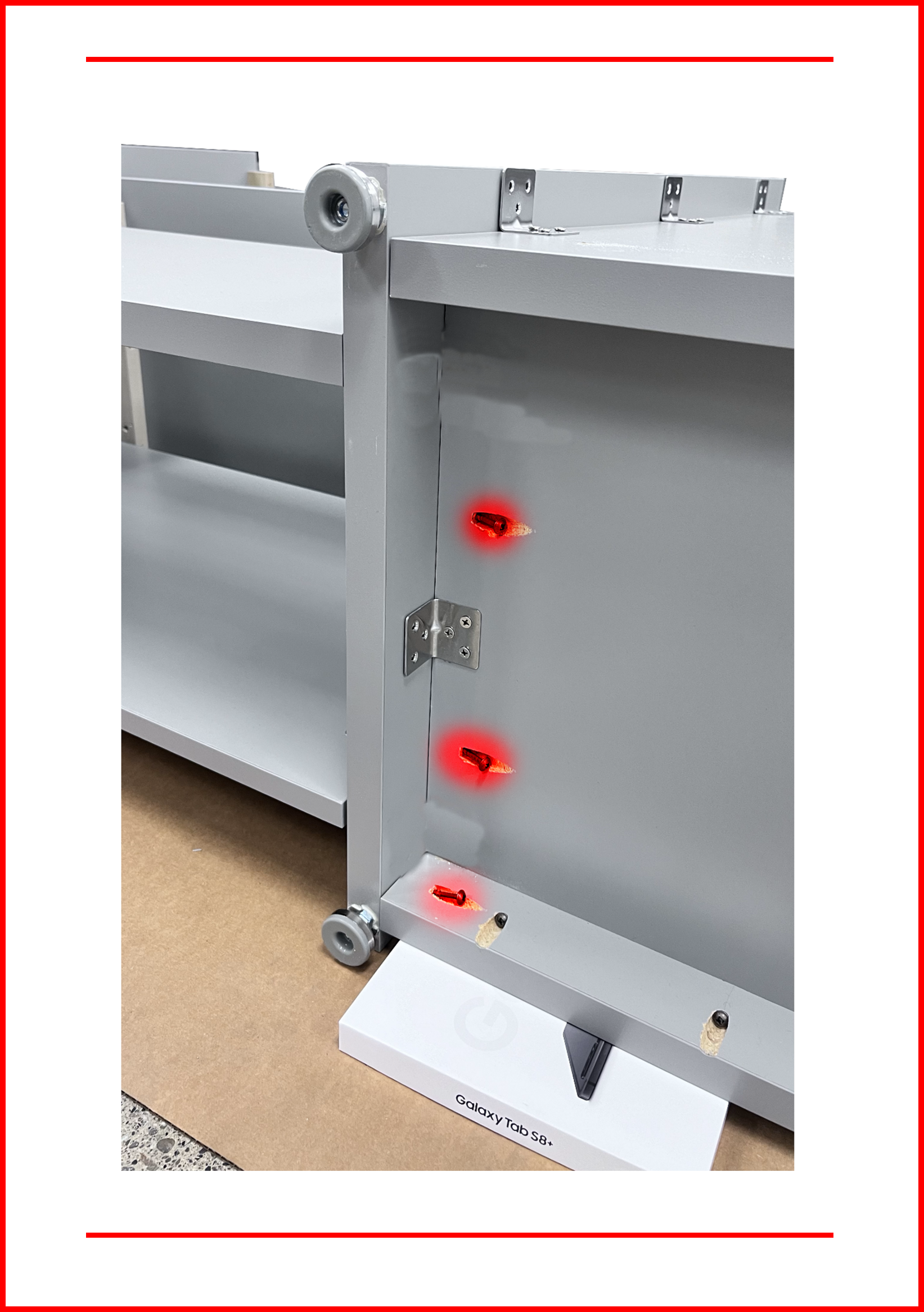
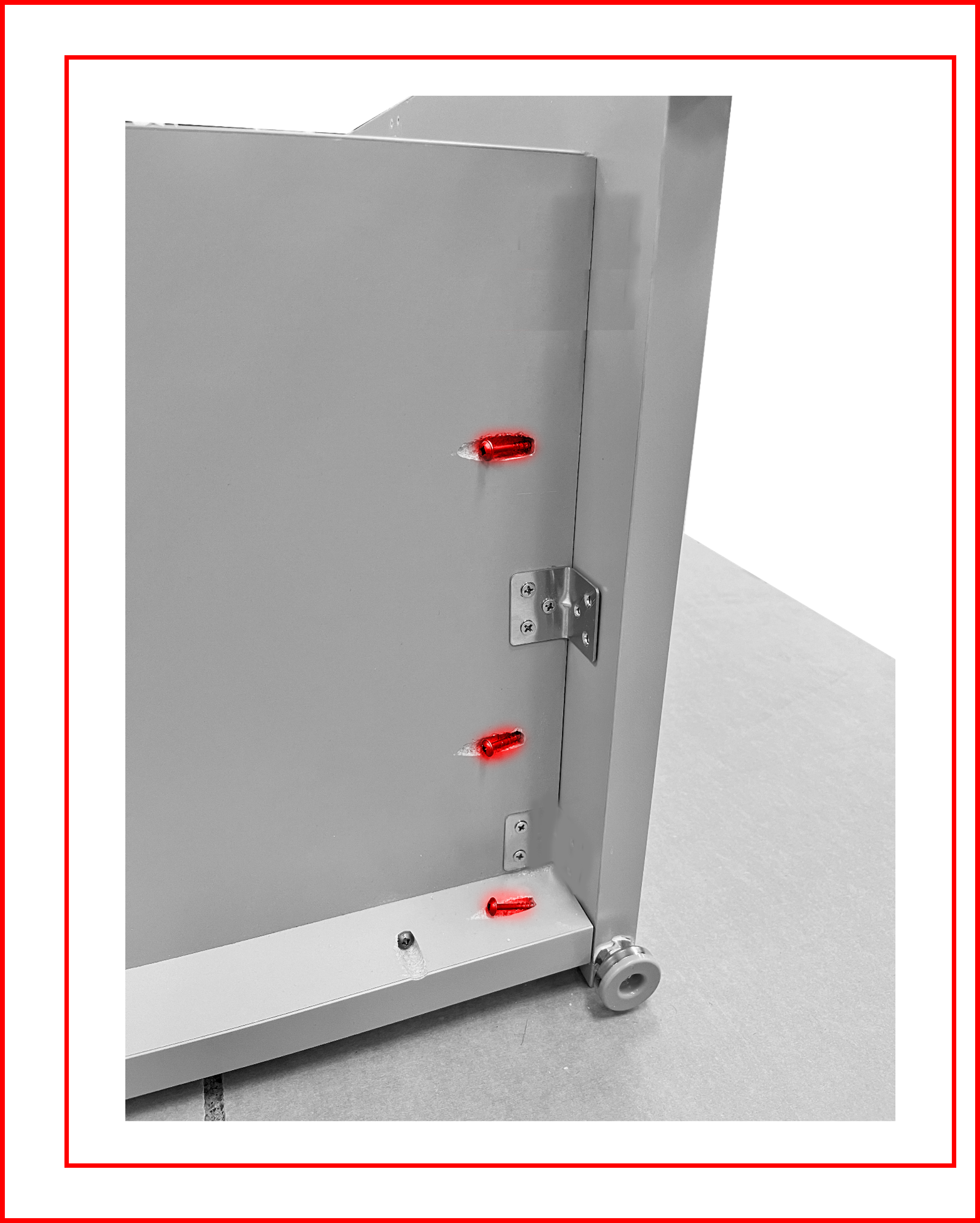
- Place 9 - 1” screws through the brackets and tighten.
Figure EA.24
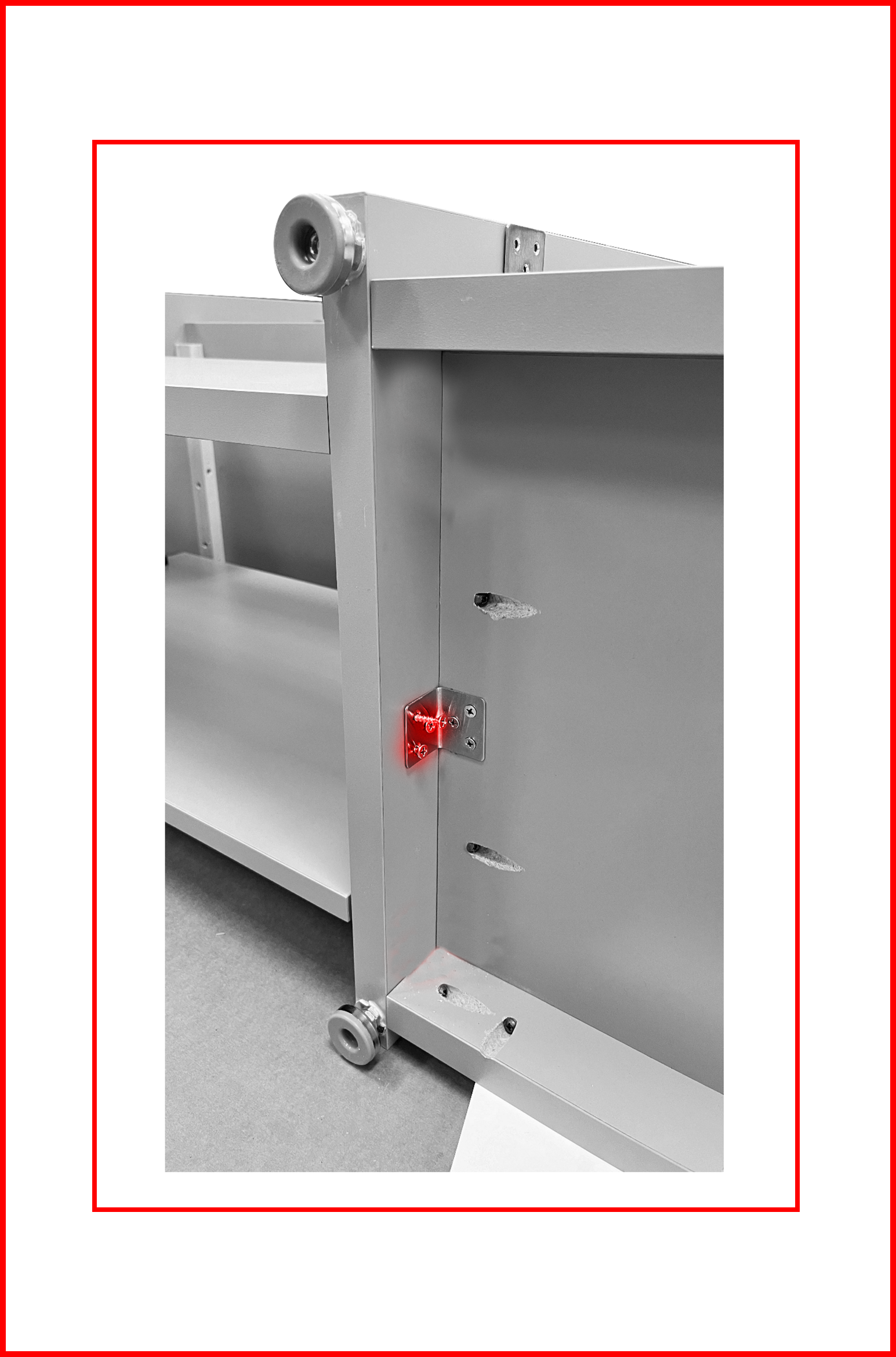
Figure EA.25
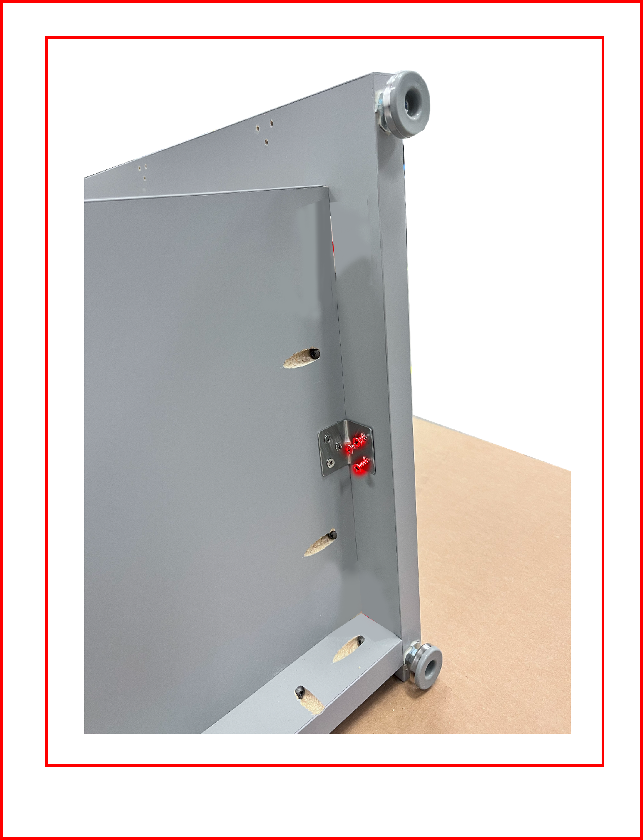
- At this point ensure all holes in all brackets have screws in them and the screws are tightened. Apart from the brackets that will mount the Top.
- Ensure all pocket hole screws are tightened.
- Ensure the 6 countersunk screws that go through the Right and Left Panels are present and tightened.
Assembling the Top
- Return the Extended Desk to the upright position. Arrange the Extended Desk and Top as shown for reference. The side with the holes will be placed facing the ground onto the Extended Desk.
⚠️ WARNING
THIS IS A TEAM LIFT OPERATION!
Figure EA.26
- Place the Top #9, alignment slots down.
- Align all the alignment pins and slots.
- Push the top down relatively gently but with force. You are aiming for pressure and not impact. You may need to persuade the legs of the desk slightly, so the slots slide over the pins and the Top sits nicely on the Extended Desk.
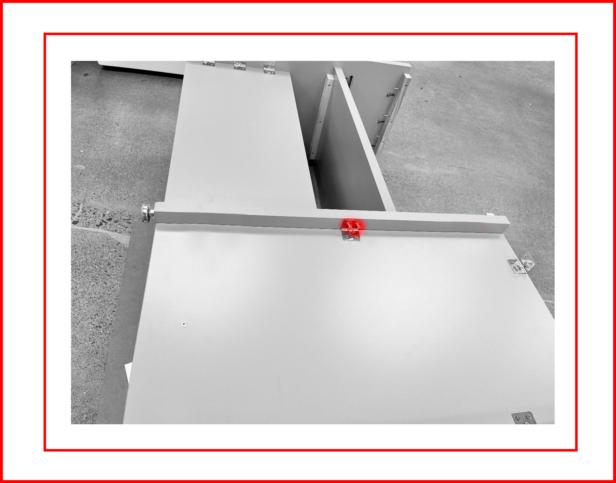
- Tighten the 9 pre-installed pocket hole screws. Tighten the 8 – preinstalled wood screws located on the underside of the wood brace in the right and left sides of the Desk. Place and tighten 1” screws through the 3 brackets on the Left Leg side. Ensure there is no gap between the legs of the Extended Desk and the Top before final tightening. If there is a gap, have a helper apply pressure from the top. DO NOT RELY ON THE SCREWS TO PULL ANY LARGE GAP CLOSED! This will strip the screw holes.
Figure EA.27
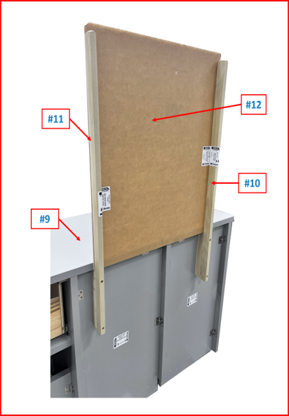
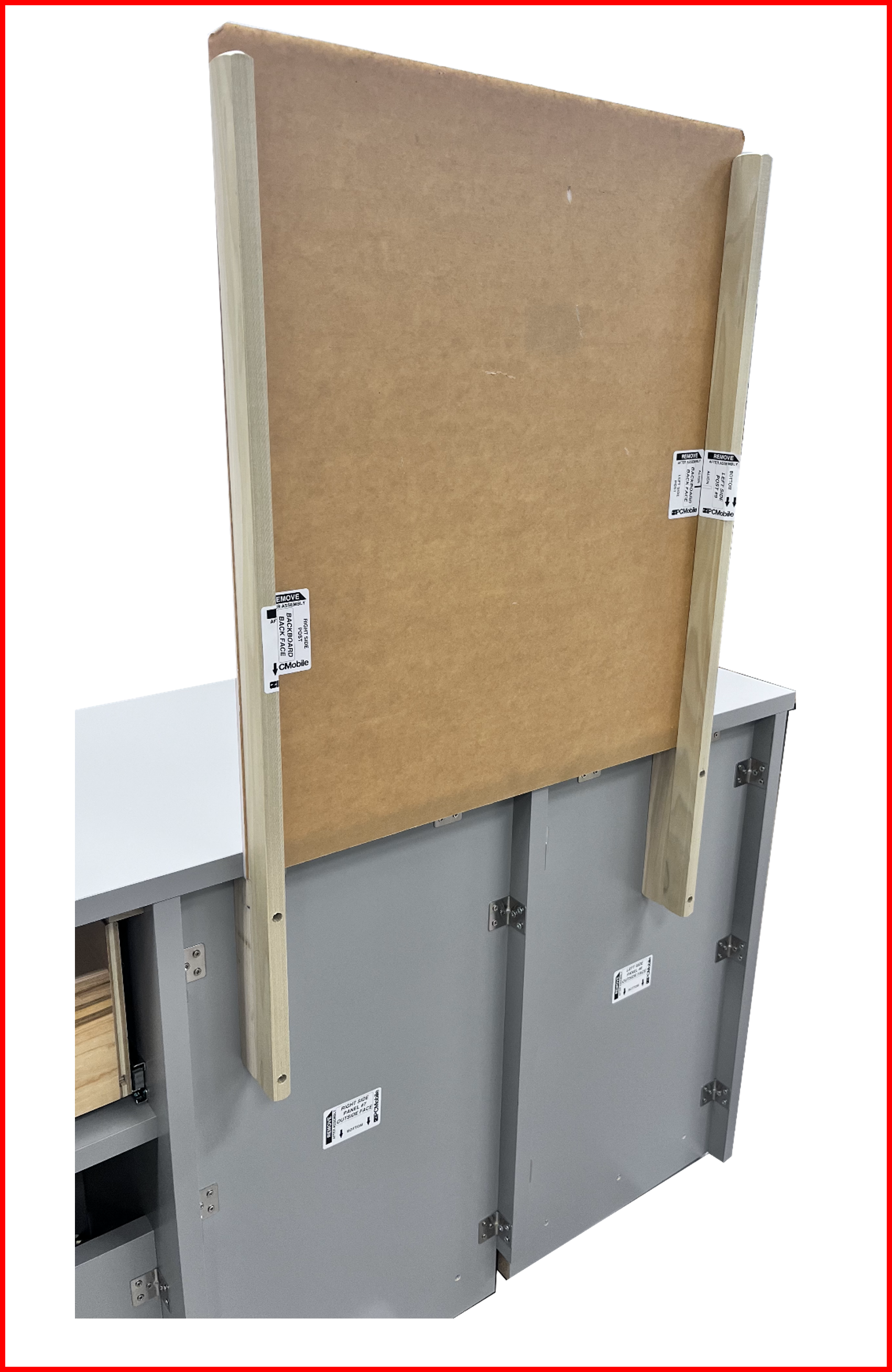
Assembling the Backboard
- Assemble the Left-Side Pole #10 and then the Right-Side Pole #11 loosely as directed by the labels affixed to the poles. Ensure the labels are oriented facing each other.
Figure EA.28
- Remove the brown protective layer from both sides of the Backboard #12 and slide the backboard between the poles and the desk oriented per the label. The two holes should be on the top facing the front of the desk.
- Place the 2 – #8 x 1” wood backboard screws thru the backboard and into the left and right poles.
- Tighten all 6 screws.
Figure EA.29
Reinstalling the Drawer
- Insert the drawer slides on the drawer into the slides on the desk.
- Close the drawer all the way.
- Ensure the drawer opens and closes fully without binding.
Unboxing RDS System Hardware 📦
RDS System Hardware should arrive as shown:
Overpack B Overview
P/N: RDS-KIT-2
Figure E1.1

Unboxing OVERPACK B
-
Removing any shrink wrap, strapping or outer box lining from
OVERPACK BBox from shipping. -
Keep box orientated as packaged on pallete skid. Opening up the top will reveal contents within:
Figure E1.2
ℹ️ NOTE
KEYSfor the Drawer and Service Door locks ofDESKare located inBOX 7and will be needed for the future assembly steps.
Contents Checklist - RDS SYSTEM HARDWARE ✅:
OVERPACK B
-
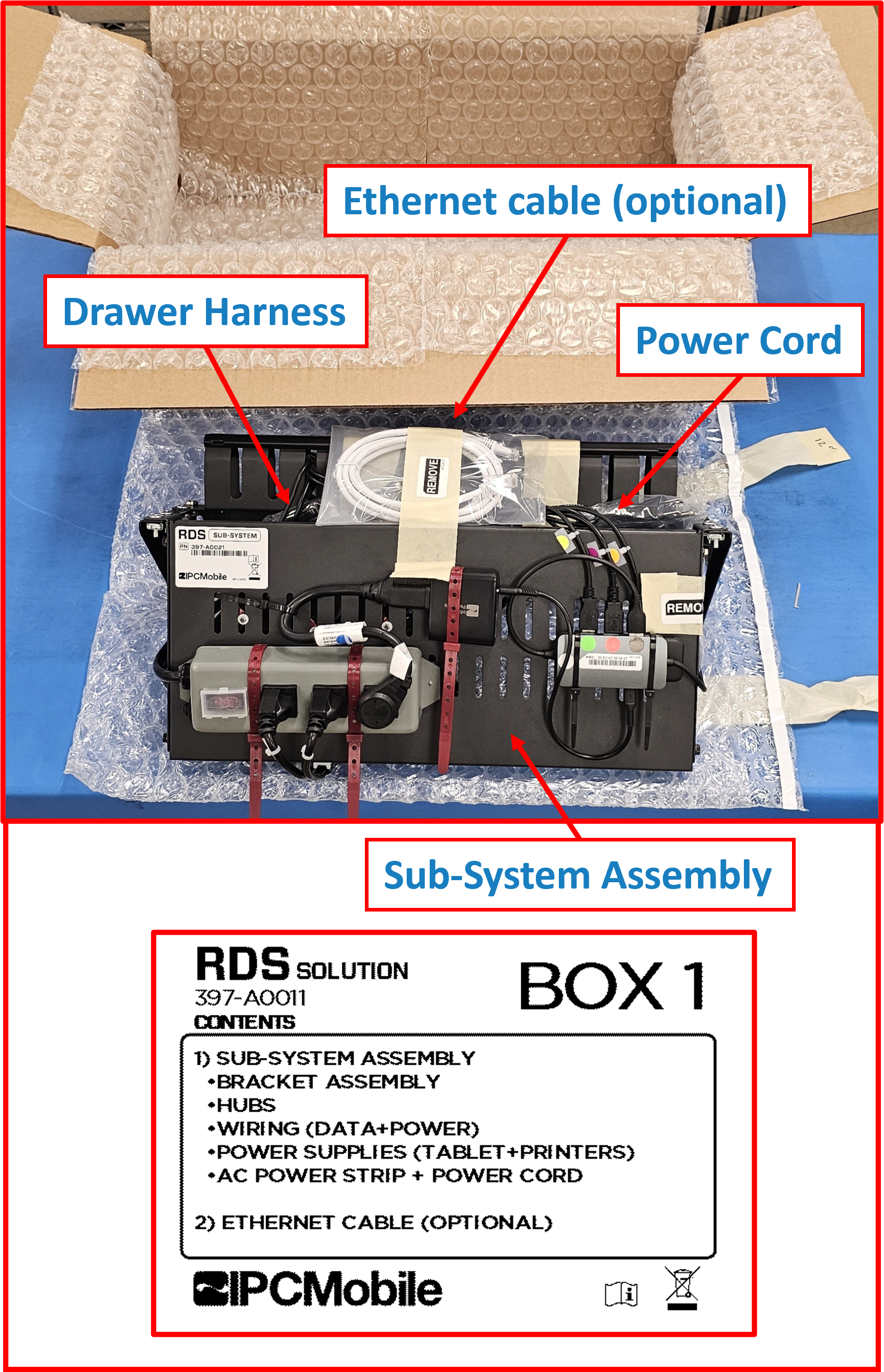
BOX 1 (SUB-SYSTEM)- ☑️
Sub-System w/ Bracket(Pre-assembled w/ USB Hubs, Power Adapters, Peripheral Data/Power Cables, and AC Power Strip) - ☑️
Drawer Cable Harness(attached to Sub-System) - ☑️
Power Cord (System)(attached to Sub-System) - ☑️
Ethernet Cable1
- ☑️
-
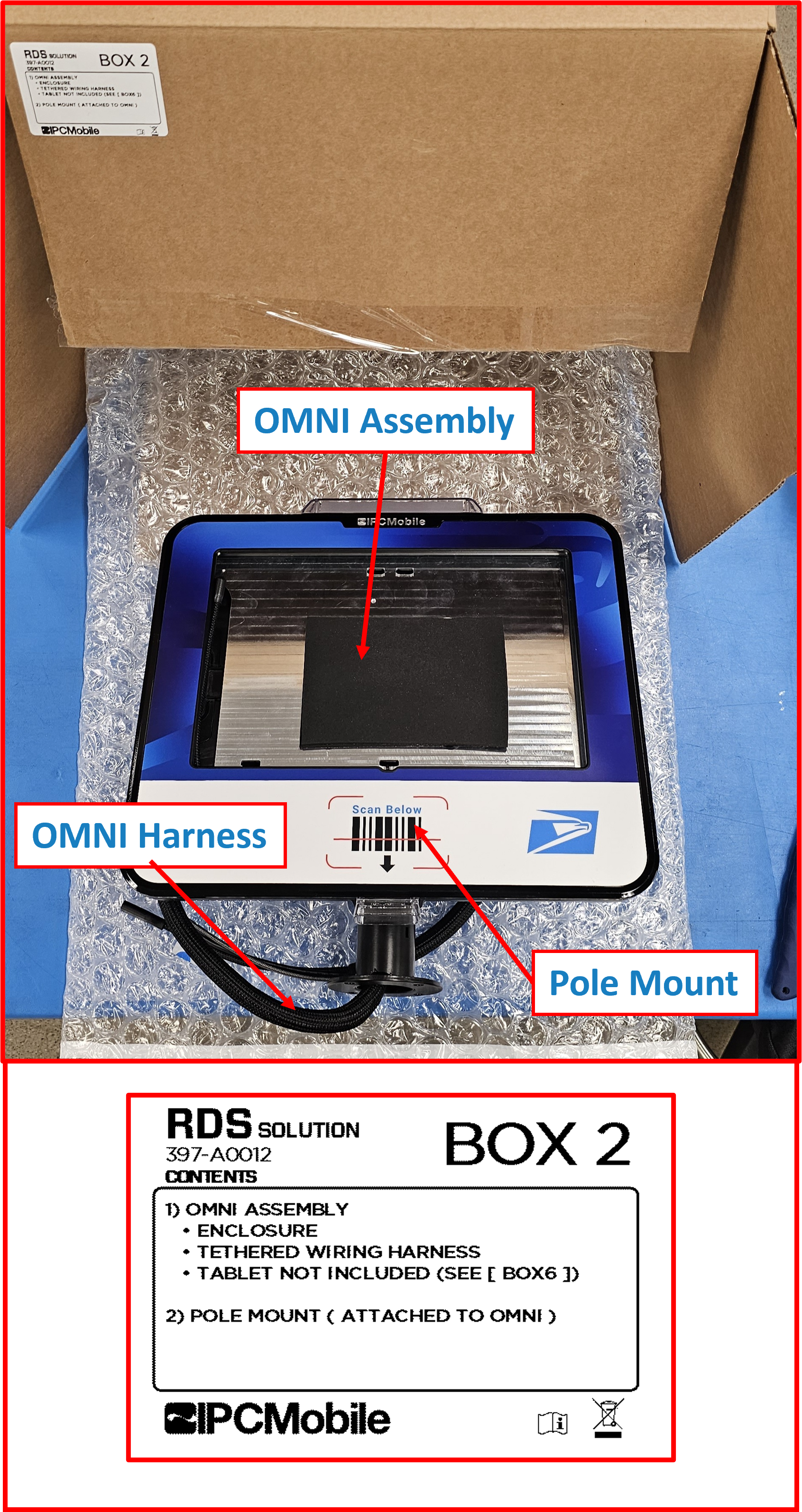
BOX 2 (OMNI + POLE MOUNT)- ☑️
OMNI Device - ☑️
OMNI Cable Harness(attached to OMNI Device) - ☑️
Pole Mount(attached to OMNI Device)
- ☑️
-
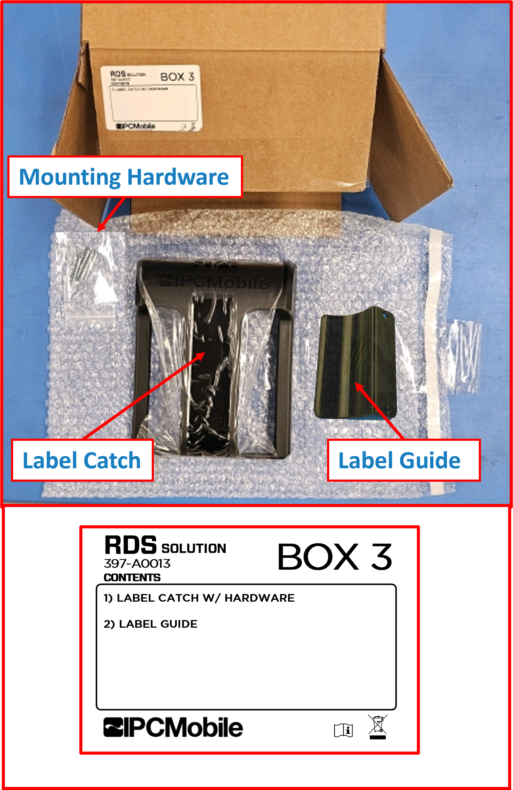
BOX 3 (LABEL CATCH)- ☑️
Label Catch - ☑️
Label Guide - ☑️
Mounting hardware screws
- ☑️ 4x |
Flathead screws- #8 x 1-1/2IN
- ☑️
-
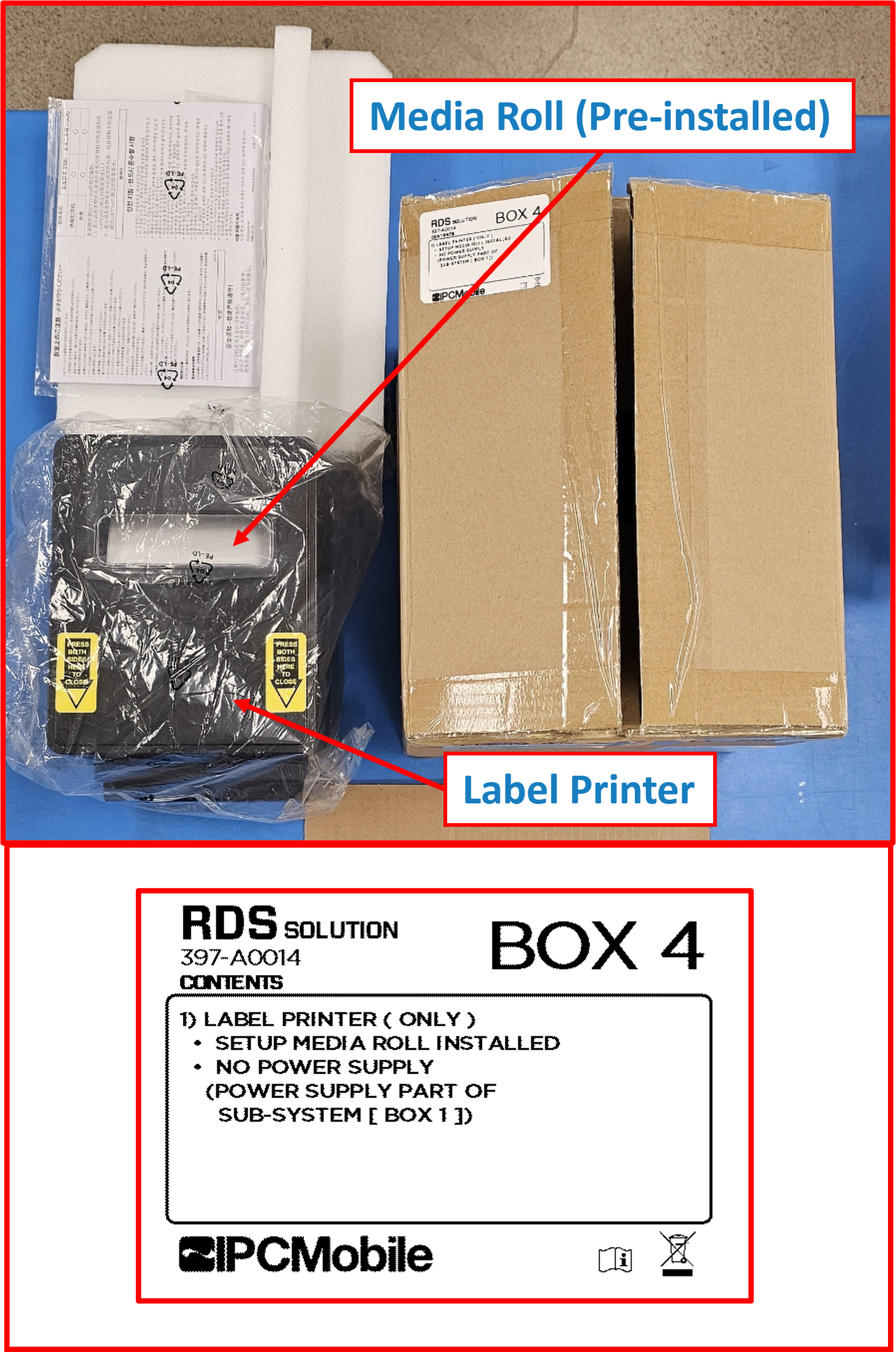
BOX 4 (LABEL PRINTER)- ☑️
Label Printer2 - ☑️
Label Media Roll(pre-installed)
- ☑️
-
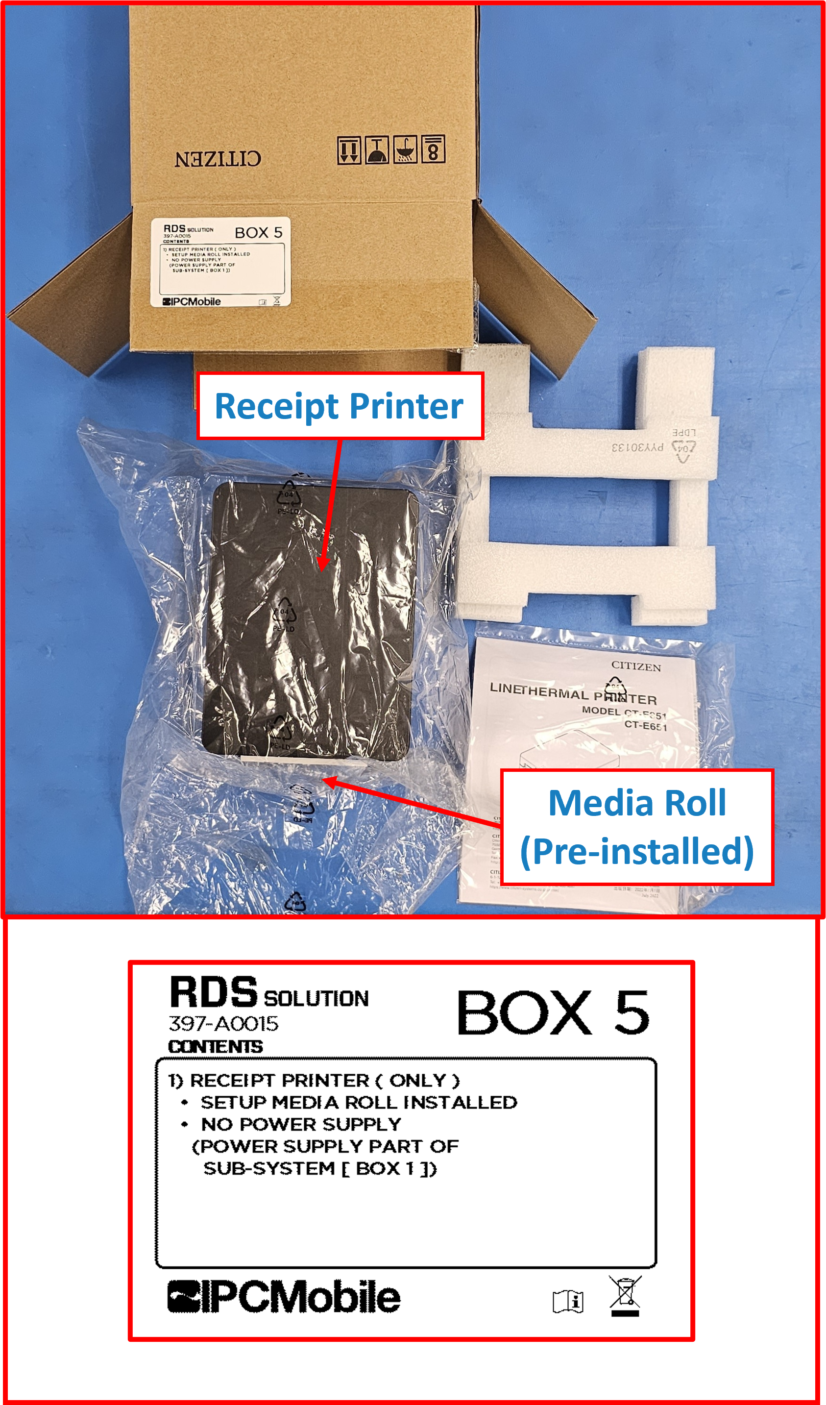
BOX 5 (RECEIPT PRINTER)- ☑️
Receipt Printer2 - ☑️
Receipt Paper Roll(pre-installed)
- ☑️
-
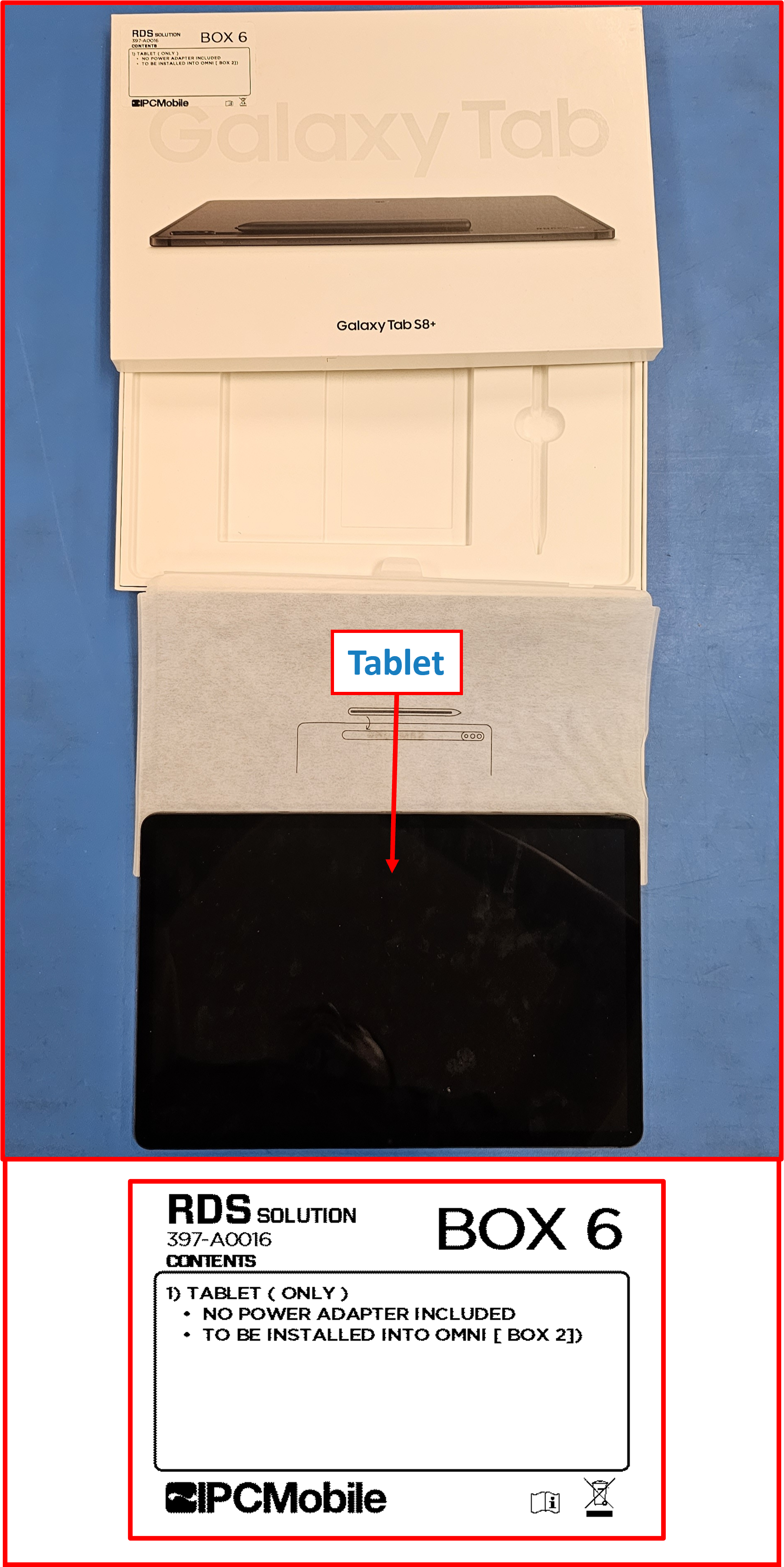
BOX 6 (TABLET)- ☑️
Tablet2
- ☑️
-
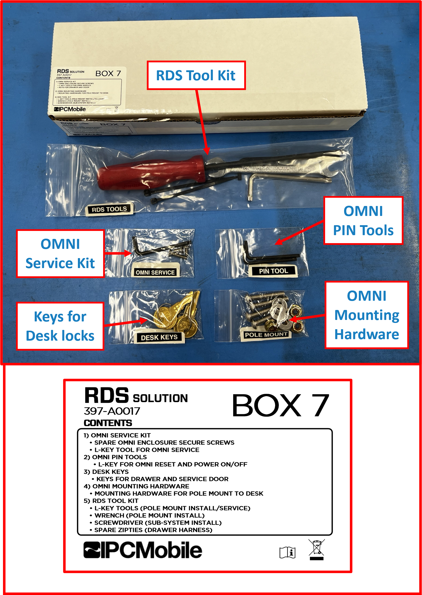
BOX 7 (HARDWARE/TOOL KITS)-
OMNI Service Kit- ☑️
Spare hardware screwsfor OMNI Tablet Service End Cap- ☑️ 2x |
Security screws (short)- M4x0.7x10MM Torx-TR Flathead - ☑️ 1x |
Security screw (long)- M4x0.7x20MM Torx-TR Flathead
- ☑️ 2x |
- ☑️
OMNI Service tool- ☑️
Torx T20TR L-key(for OMNI Tablet Service End Cap Security screws)
- ☑️
- ☑️
-
Pin Tool Kit- ☑️ 2x |
Torx T15TR L-key(OMNI reset pin tool & for screws securing OMNI to Pole Mount)
- ☑️ 2x |
-
Desk Keys Pack- ☑️ 2x sets |
Keysfor Desk Locks 🔑🔑🔑🔑 3
ℹ️ NOTE
Keys are identical and work for bothDrawerandService Doorlocks. - ☑️ 2x sets |
-
RDS Tool Kit- ☑️
Screwdriver- Phillips No.2, 6IN shaft - (for tightening Sub-System mounting screws) - ☑️
Wrench- Two-headed, Open-end - 3/8IN x 7/16IN` - (for installing Pole Mount to Desk - Locknuts) - ☑️
Hex 5/32IN L-key(for installing Pole Mount to Desk - Buttonhead screws) - ☑️
Torx T30TR L-key(for adjusting Pole Mount pivot tension) - ☑️ 2x sets |
4IN releasable zipties(spares for in-Drawer harness securing)
- ☑️
-
OMNI Pole Mount Mounting Hardware- ☑️ 4x |
Buttonhead screws- 1/4-20 x 1-1/2IN - ☑️ 4x |
Flat Washers- for 1/4IN screws - ☑️ 4x |
Locknuts- 1/4-20 flanged
- ☑️ 4x |
-
-
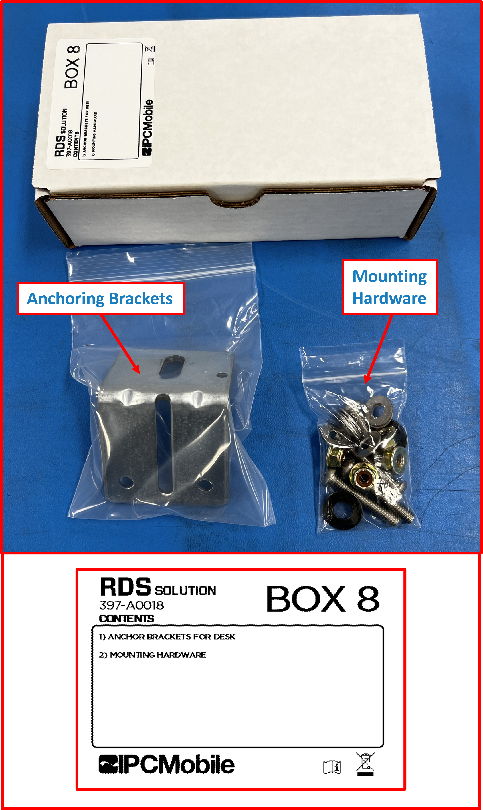
BOX 8 (ANCHORING KIT)- ☑️ 2x |
Slotted L-Brackets(for anchoring Desk to wall or floor) - ☑️ 4x |
Buttonhead screws- 1/4-20 x 1-1/2IN - ☑️ 8x |
Flat Washers (large)- for 1/4IN screws - ☑️ 4x |
Locknuts- 1/4-20 flanged - ☑️ 6x |
Flat Washers (small)- 0.5IN OD, for #8 screws
- ☑️ 2x |
-
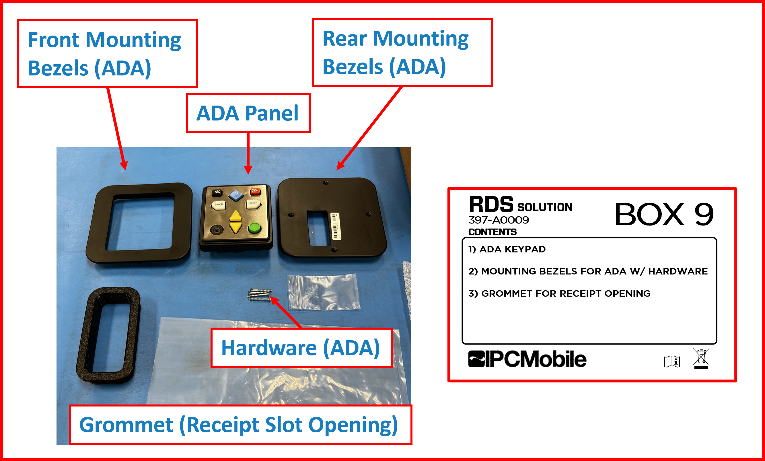
BOX 9 (ADA/RECEIPT GROMMET)- ☑️
ADA Panel - ☑️
Front Bezel (ADA) - ☑️
Rear Bezel (ADA) - ☑️
Grommet (Receipt Opening in Drawer) - ☑️
Mounting hardware screws (ADA)
- ☑️ 4x |
Flathead screws- #6 x 1-1/4IN
- ☑️
-
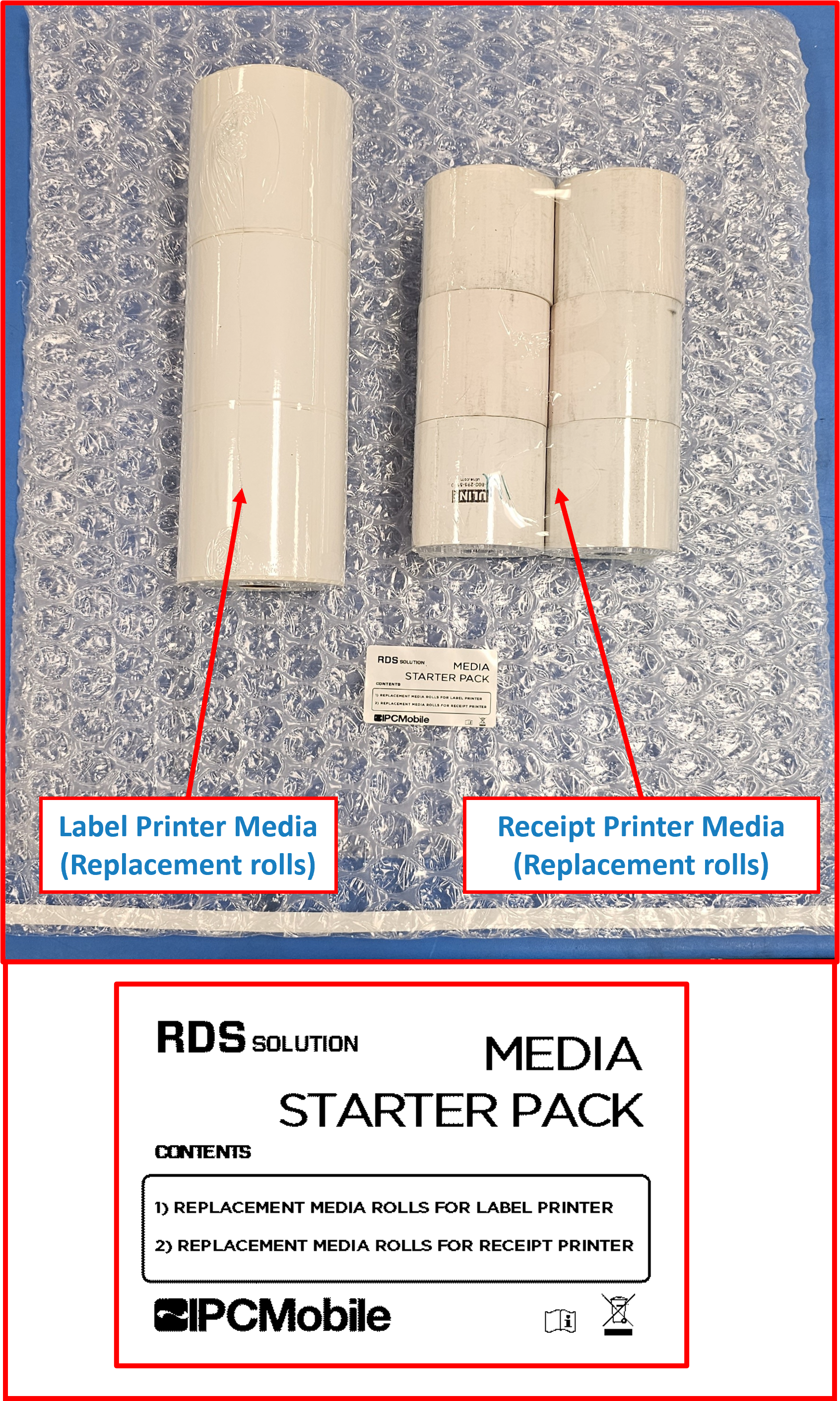
MEDIA STARTER PACK- ☑️ 3x |
Label Media Rolls - ☑️ 6x |
Receipt Paper Rolls
- ☑️ 3x |
Unboxing Contents (OVERPACK B)
- Remove contents from the following packaging:
-
BOX 1 (Sub-System)
Figure E1.3
ℹ️ NOTE
Take care to remove all temporary tape and poly bags used to secure/protect contents during shipping --> Labeled "REMOVE"
-
BOX 2 (OMNI + Pole Mount)
Figure E1.4
ℹ️ NOTE
Take care to remove all temporary tape and poly bags used to secure/protect contents during shipping.
-
BOX 3 (Label Catch)
Figure E1.5
-
BOX 4 (Label Printer)
Figure E1.6
-
BOX 5 (Receipt Printer)
Figure E1.7
-
BOX 6 (Tablet)
Figure E1.8
-
BOX 7 (Hardware/Tool Kits)
Figure E1.9
-
BOX 8 (Anchoring Kit)
Figure E1.10
-
BOX 9 (ADA/Receipt Grommet)
Figure E1.11
-
MEDIA STARTER PACK (Replacement Print Media Rolls)
Figure E1.12
Installation 🔧
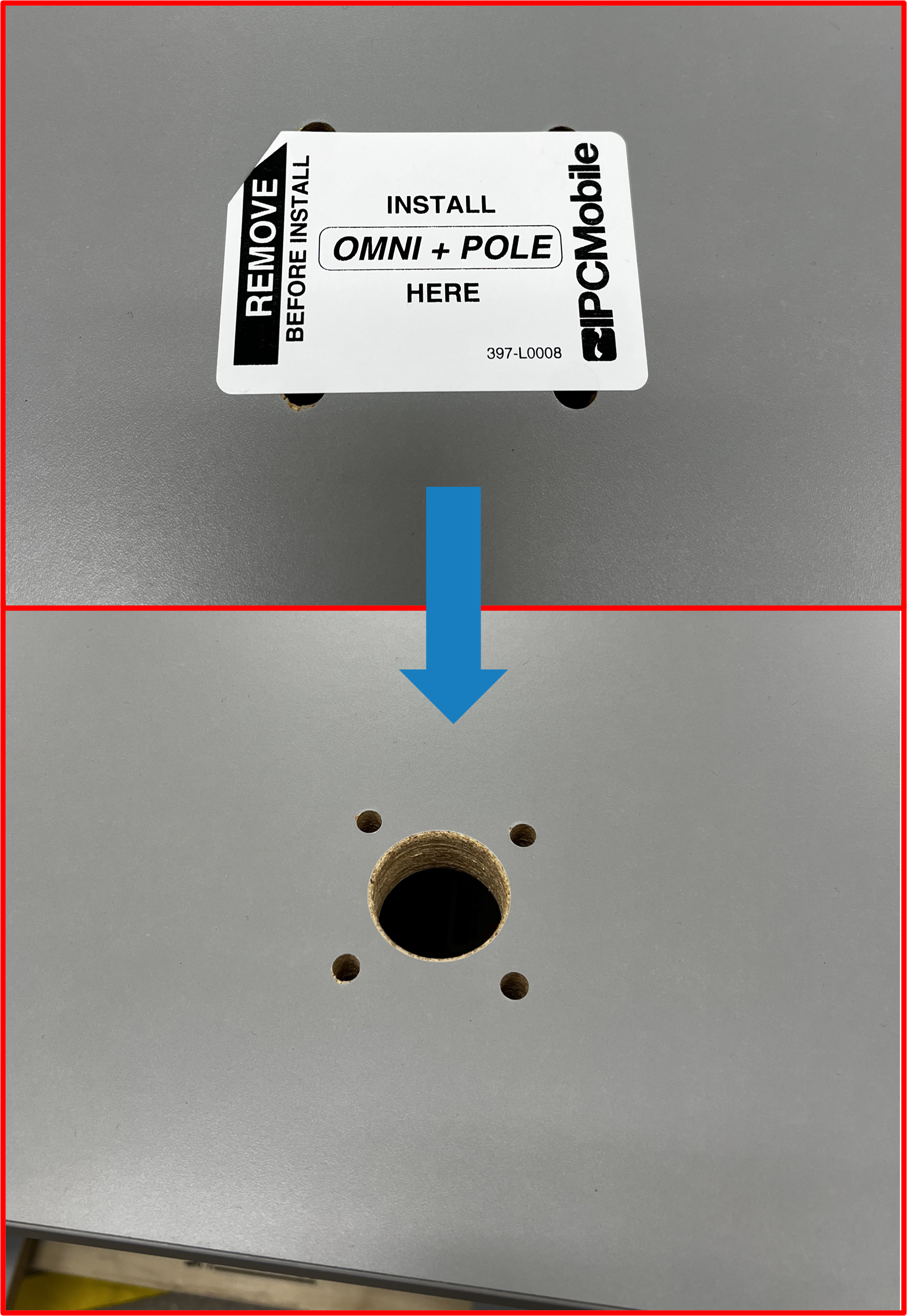
Step 1 | Install OMNI + POLE MOUNT Assembly onto DESK
- Note install location for
OMNI + POLE MOUNTon countertop ofDESK. Remove temporary label.
Figure E2.1
- Route
OMNI cable harnessthru the large hole in theDESKcountertop as shown.
Figure E2.2
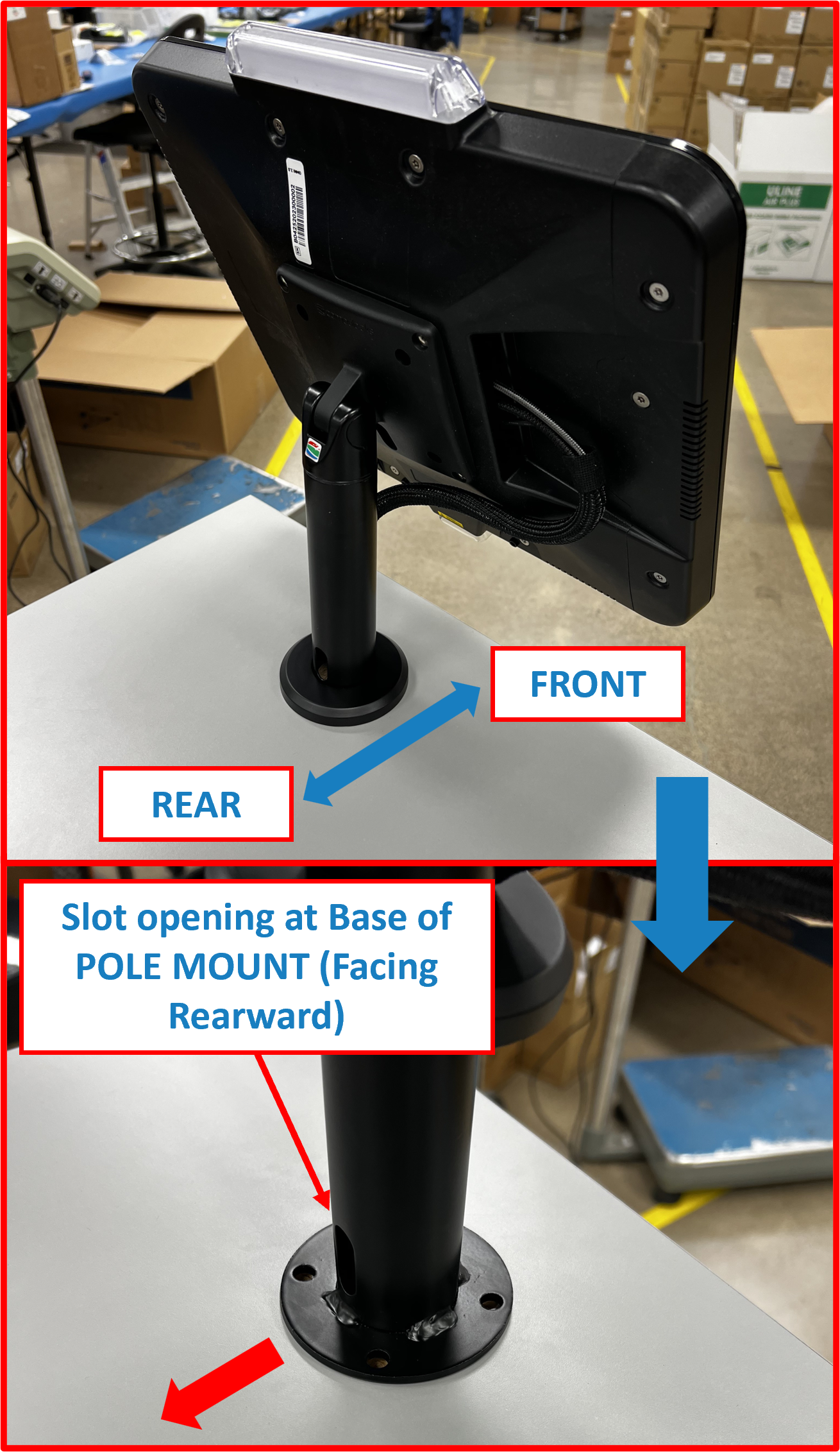
- Place base rim of
OMNI + POLE MOUNTover openings and align the 4 mounting holes on countertop ofDESK.
ℹ️ NOTE
Take care to align with slot at the base of thePOLE MOUNTrearward facing andOMNIorientated as shown.
Figure E2.3
- Using supplied hardware and tools (found in
BOX 7), install one (1)button head screwfrom topside thruPOLE MOUNTrim and mounting hole inDESKcountertop as shown. Thelocknutandwasherwill be installed on the underside. Loosely tighten bolt assembly using5/32” hex L-key(supplied) and7/16” wrench(supplied) until base ofPOLE MOUNTrim is seated againstDESKcountertop.
ℹ️ NOTE
Recommened to unlock and extendDrawerat this point to gain access to underside ofDESKcountertop.
Figure E2.4
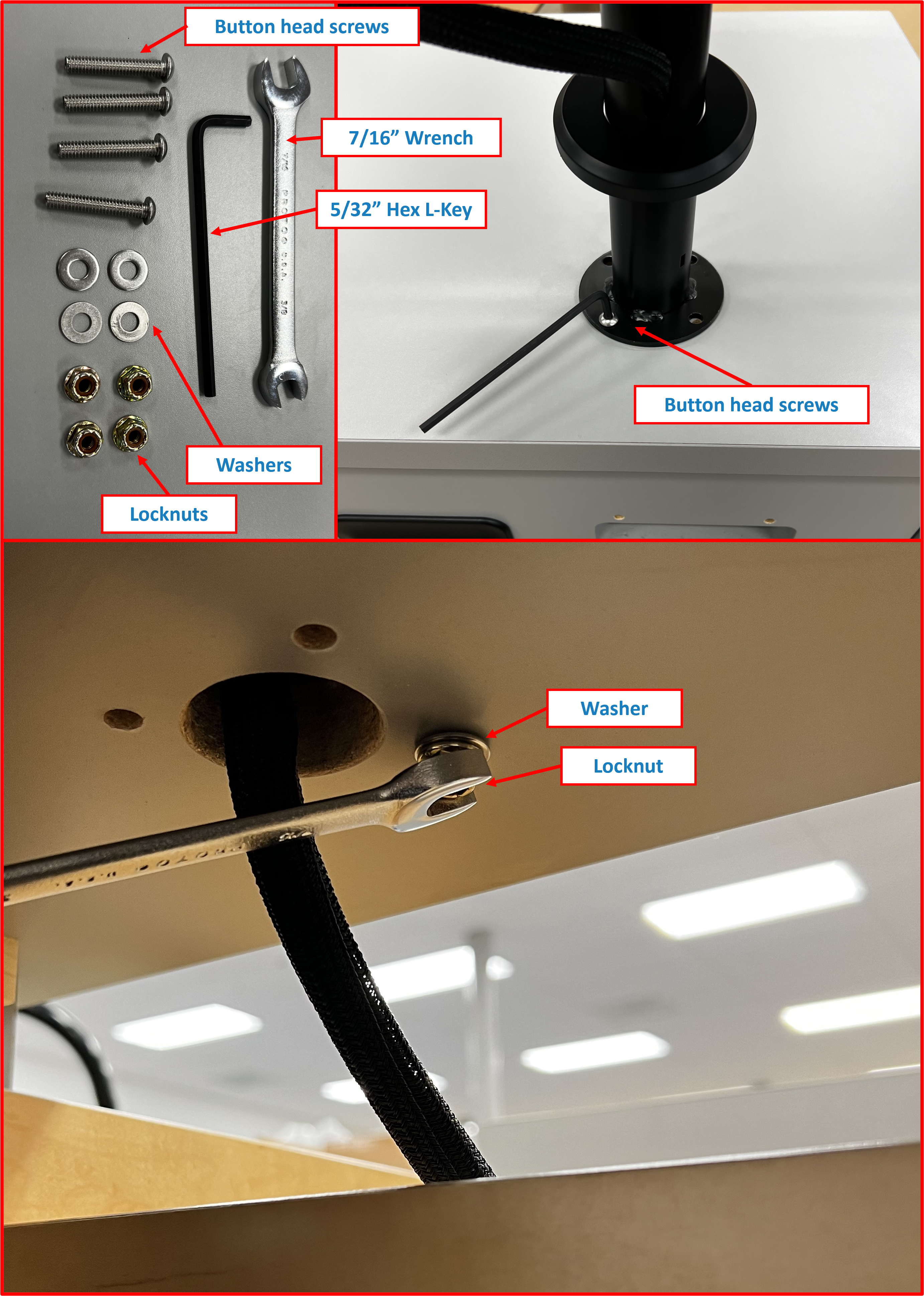
- Repeat Step 4 for the remaining screws.
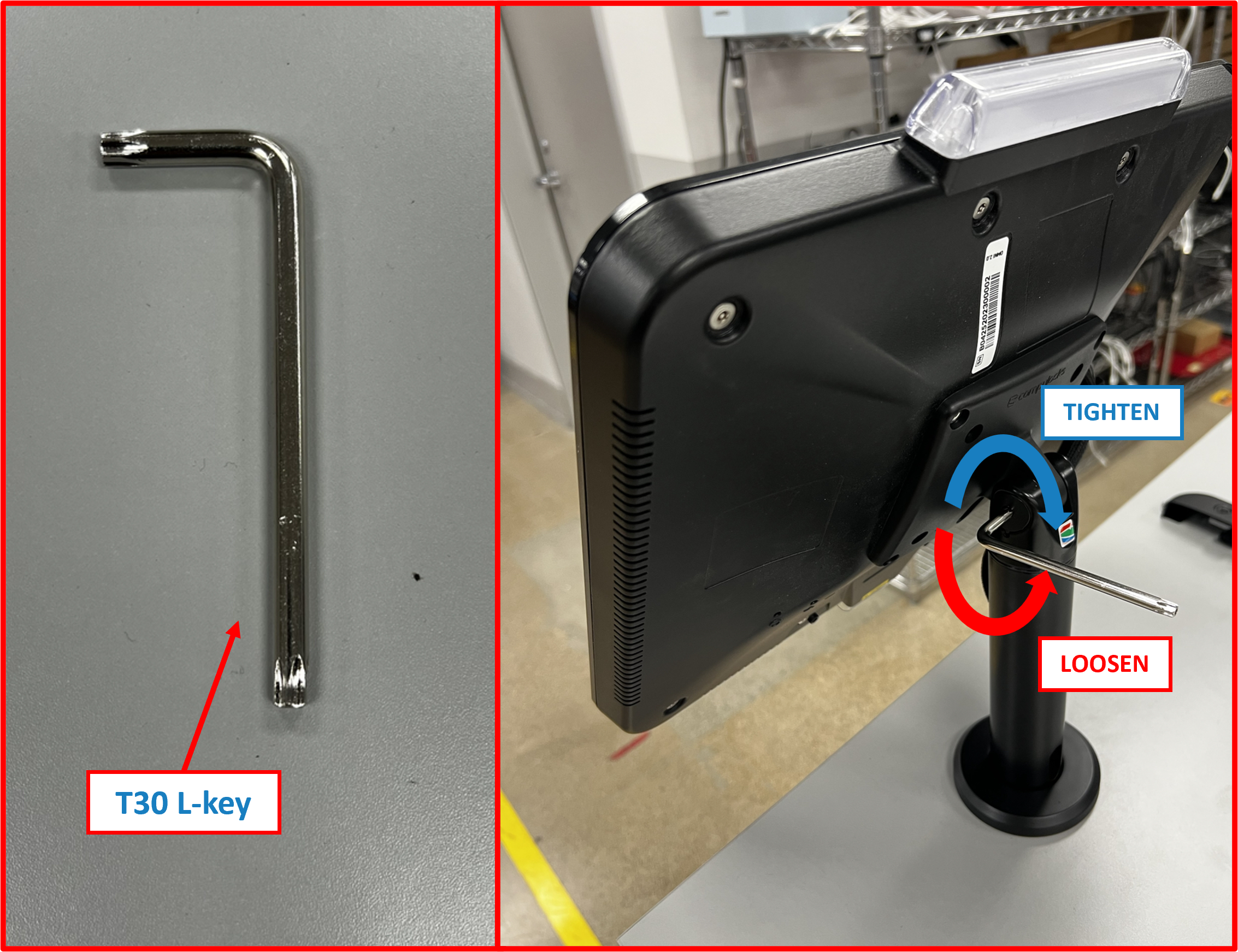
- Once all screws, nuts, and washers are installed, tighten all four (4) fastener sets to secure
OMNI + POLE MOUNTtoDESKcountertop.
ℹ️ NOTE
Take care to twist and tiltOMNIinto optimal orientation at this point. Adjust pole mount tilt tension as needed if too loose or too tight using supplied T30 torx L-key.
Figure E2.5
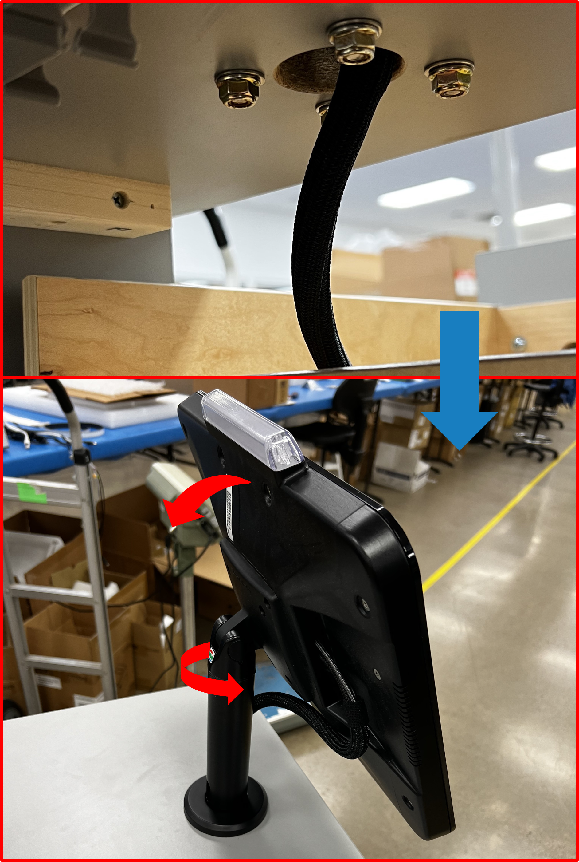
Figure E2.6
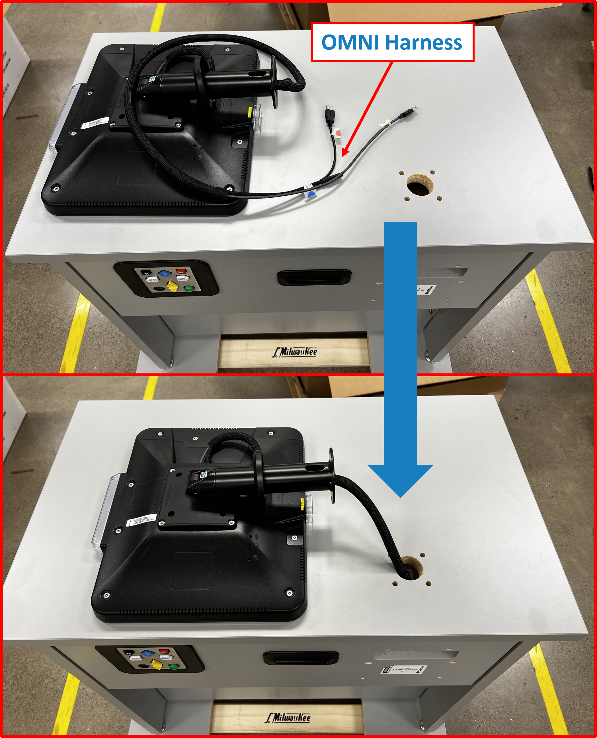
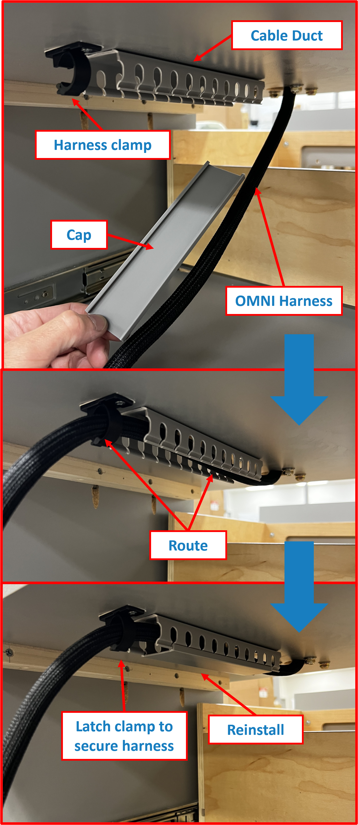
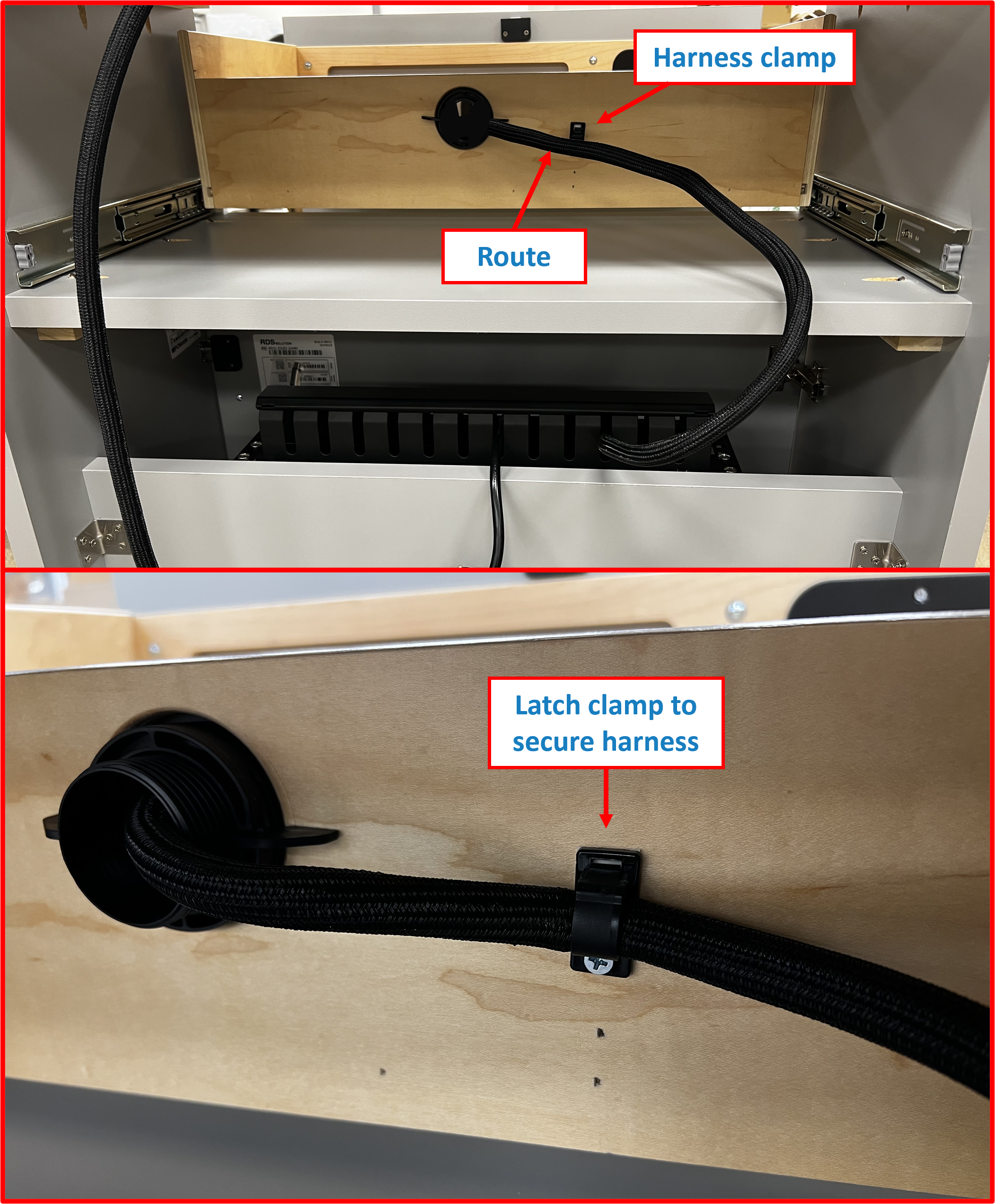
Step 2 | Route OMNI Cable Harness
- Extend
Drawerfully open to gain access to underside ofDESKcountertop. - From the back side, remove cable duct
capand routeOMNI Cable Harnessaccordingly. - Reinstall cable duct
capand secureOMNI Cable Harnessby latching theharness clamp4.
Figure E2.7
ℹ️ NOTE
At this stage,OMNI cable harnessshould be staged as shown.
Figure E2.8
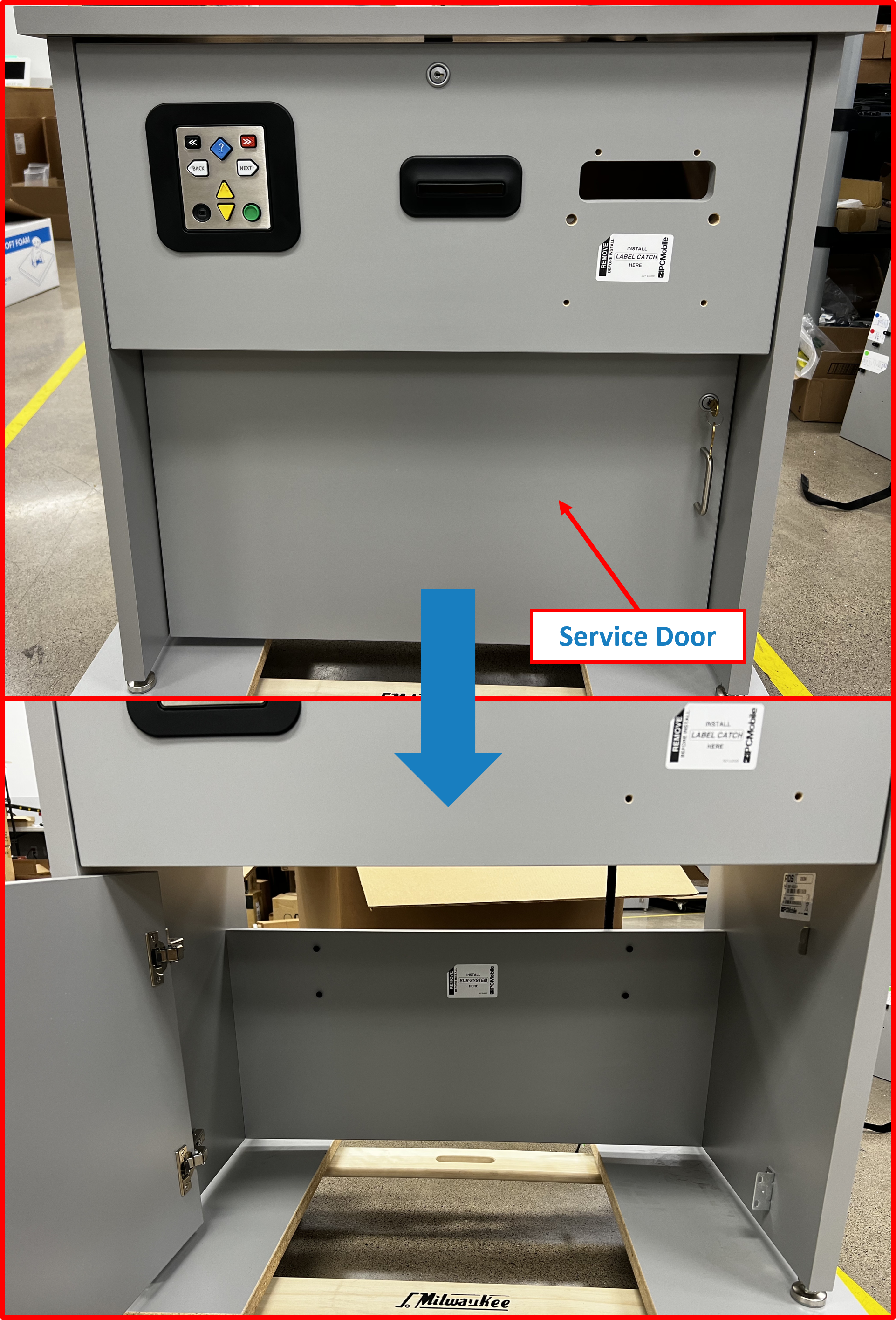
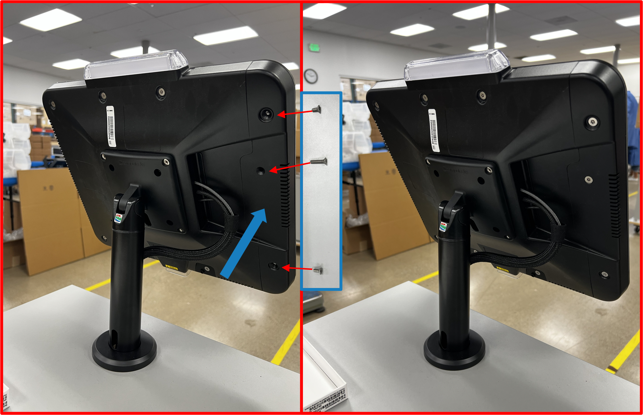
Step 3 | Install SUB-SYSTEM + BRACKET Assembly onto DESK
- Open lower
Service DoorofDESK.
Figure E2.9
- Note install location for
SUB-SYSTEM + BRACKET.
Figure E2.10
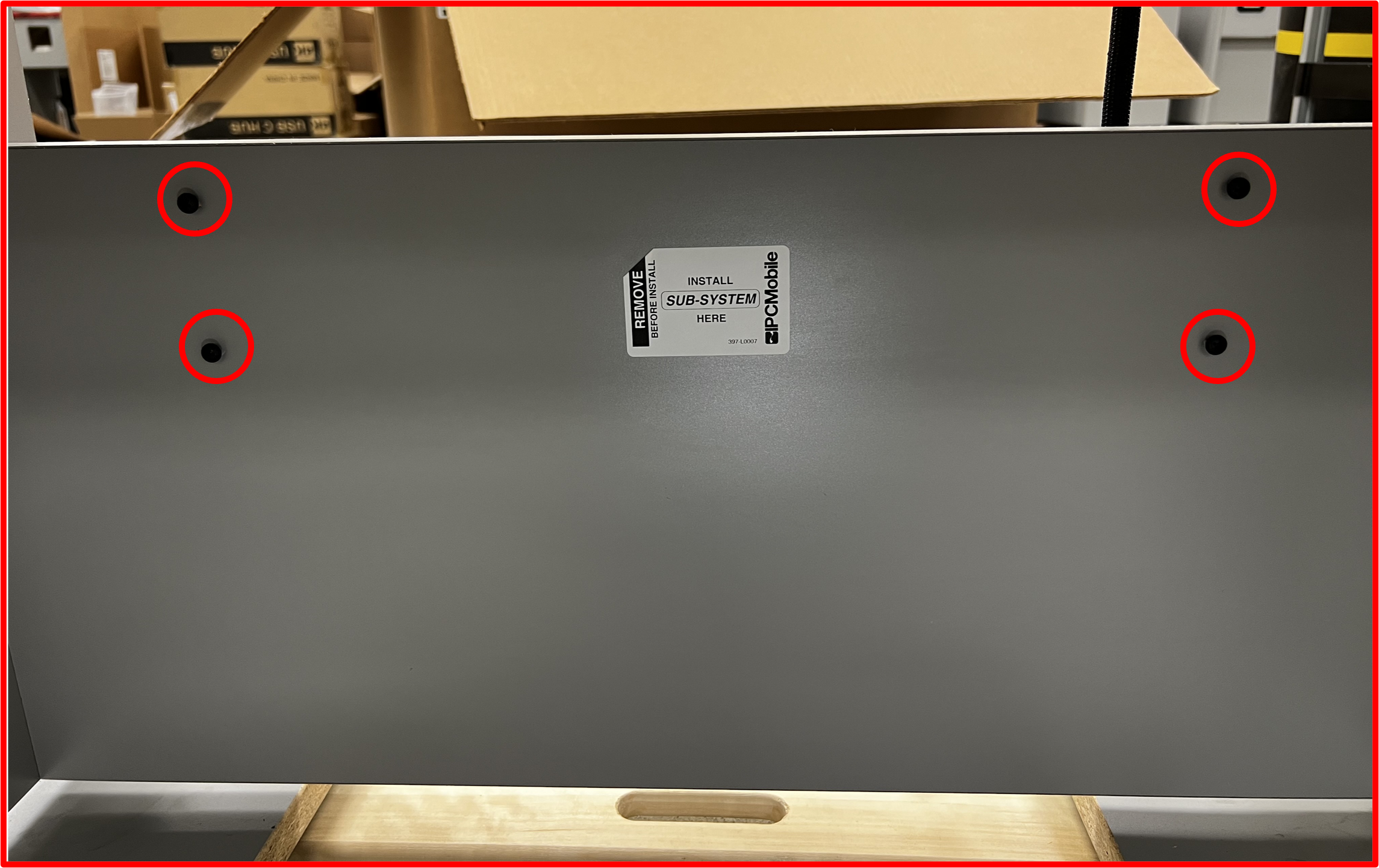
- Place
SUB-SYSTEM + BRACKETonto the four (4) pre-installed screws.
Figure E2.11
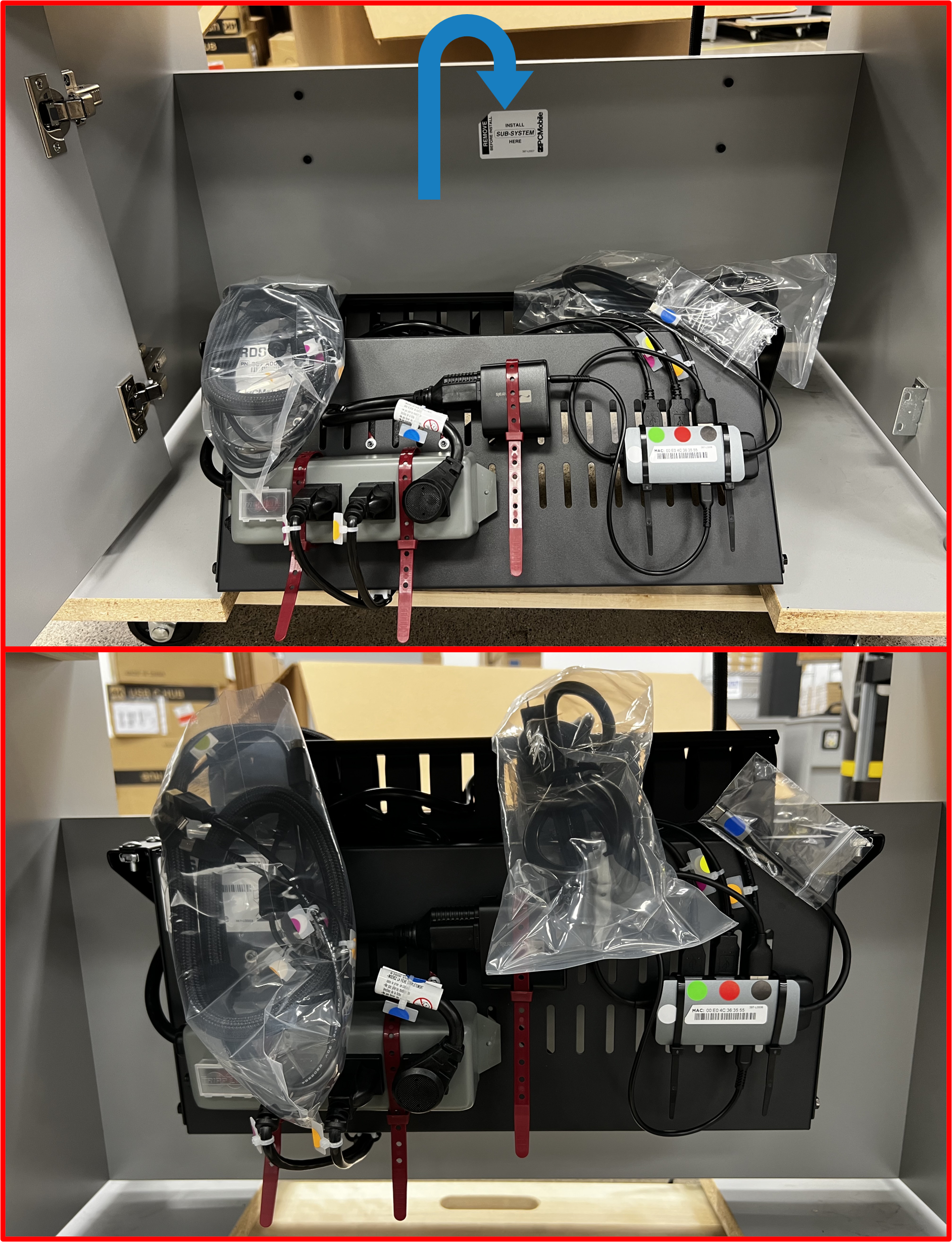
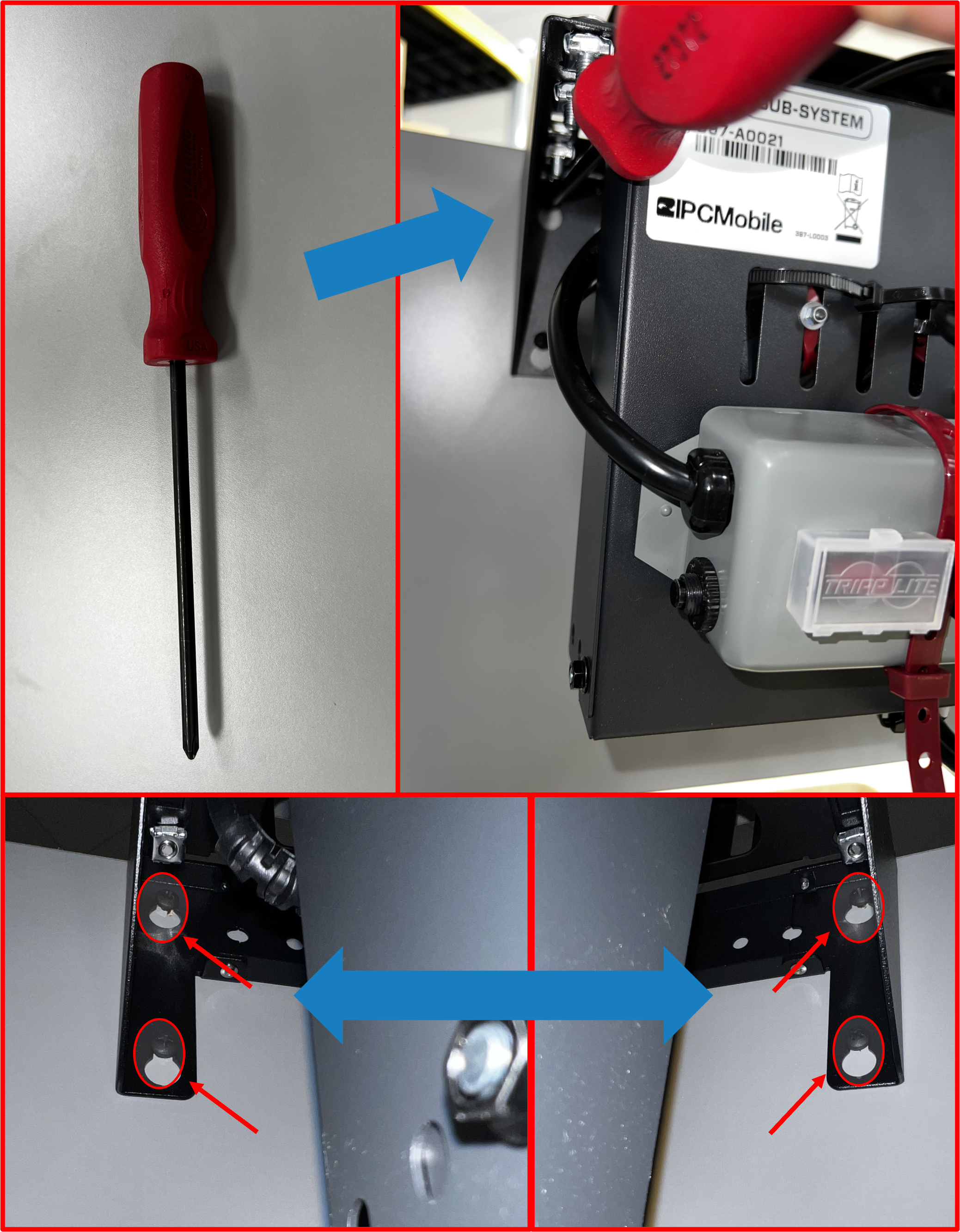
- Using long-tip
screwdriver(supplied inBOX 7), tighten all four (4) screws to secureSUB-SYSTEM + BRACKETtoDESK.
Figure E2.12
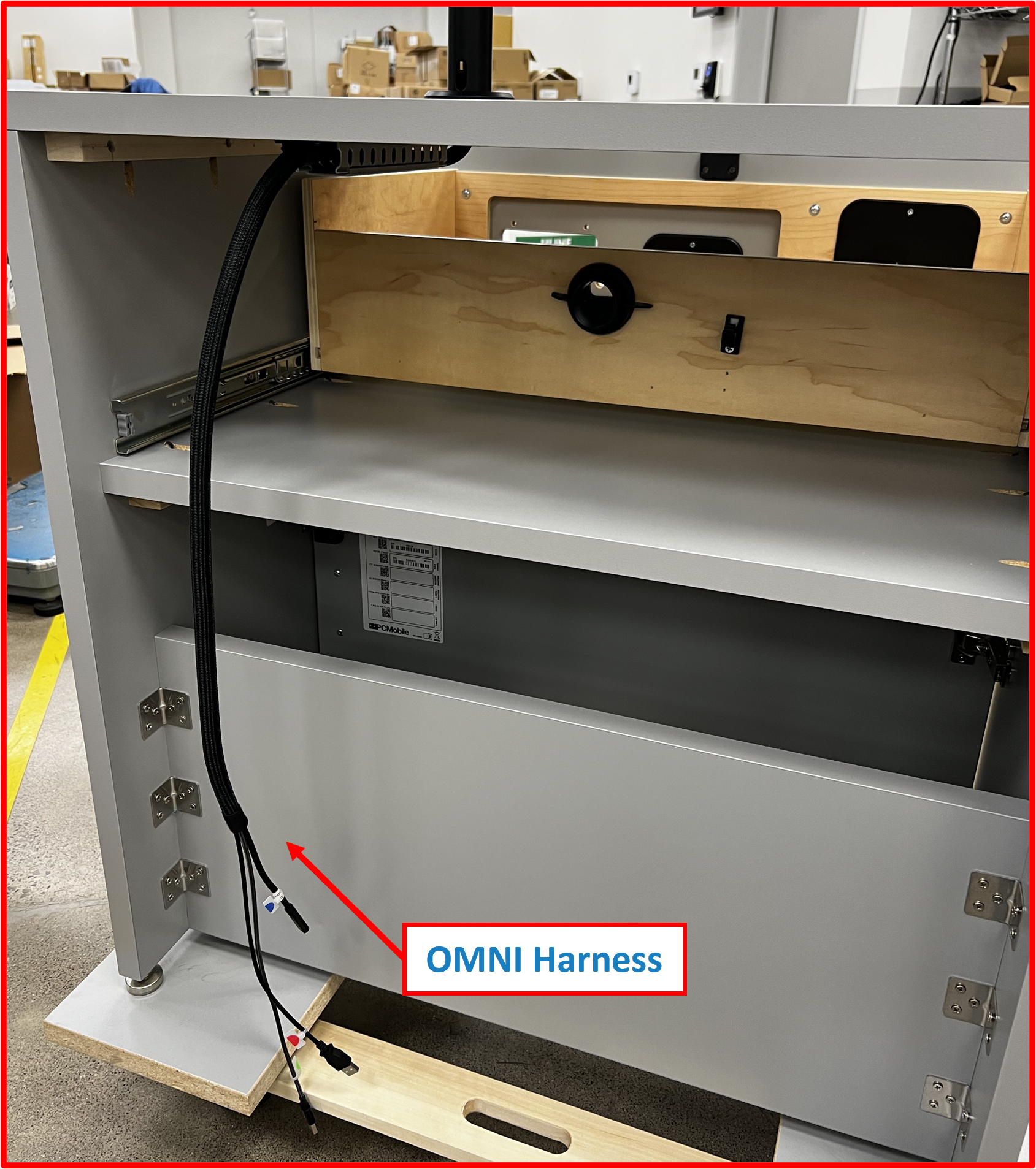
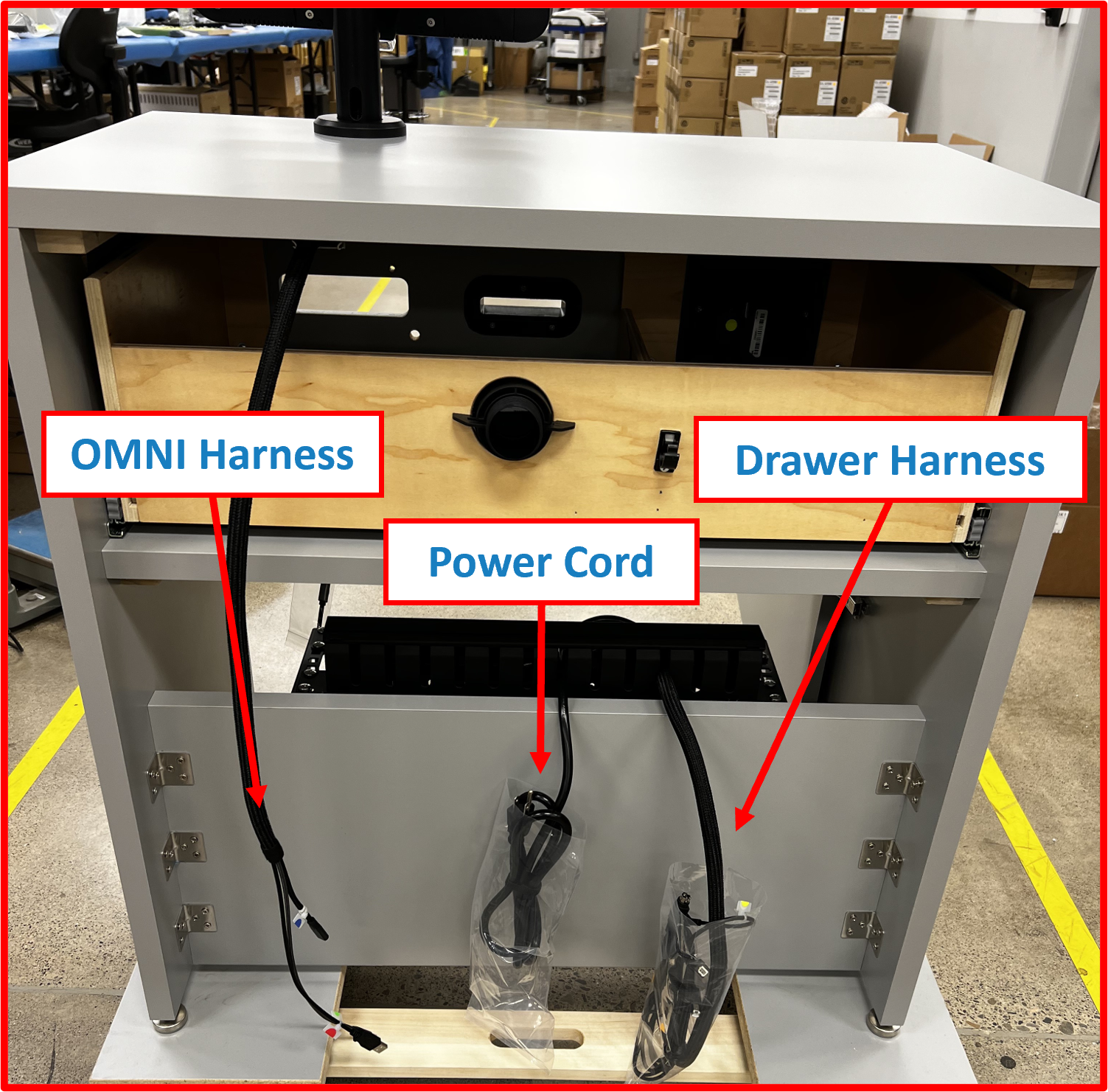
ℹ️ NOTE
At this stage, the three cable harnesses (OMNI Harness,Drawer Harness, andPower Cord) should be staged as shown:
Figure E2.13
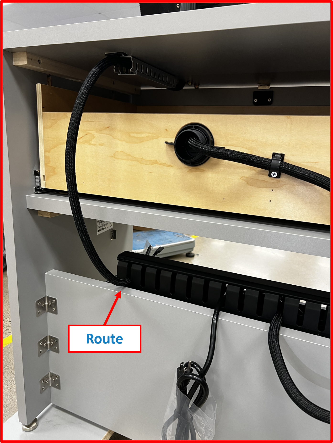
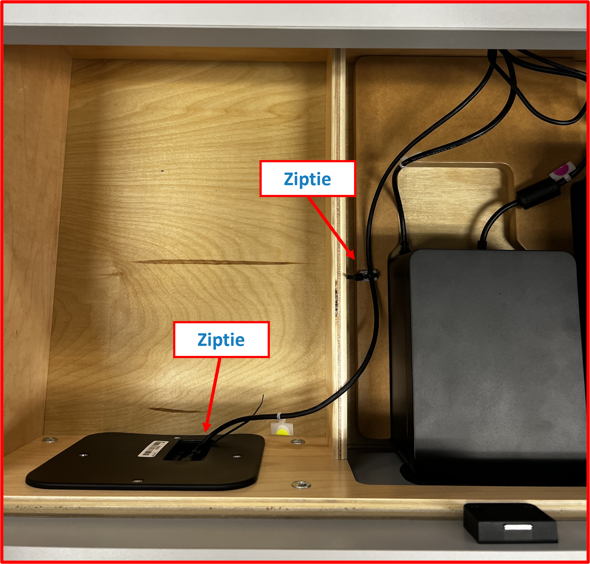
Step 4 | Route Drawer Harness
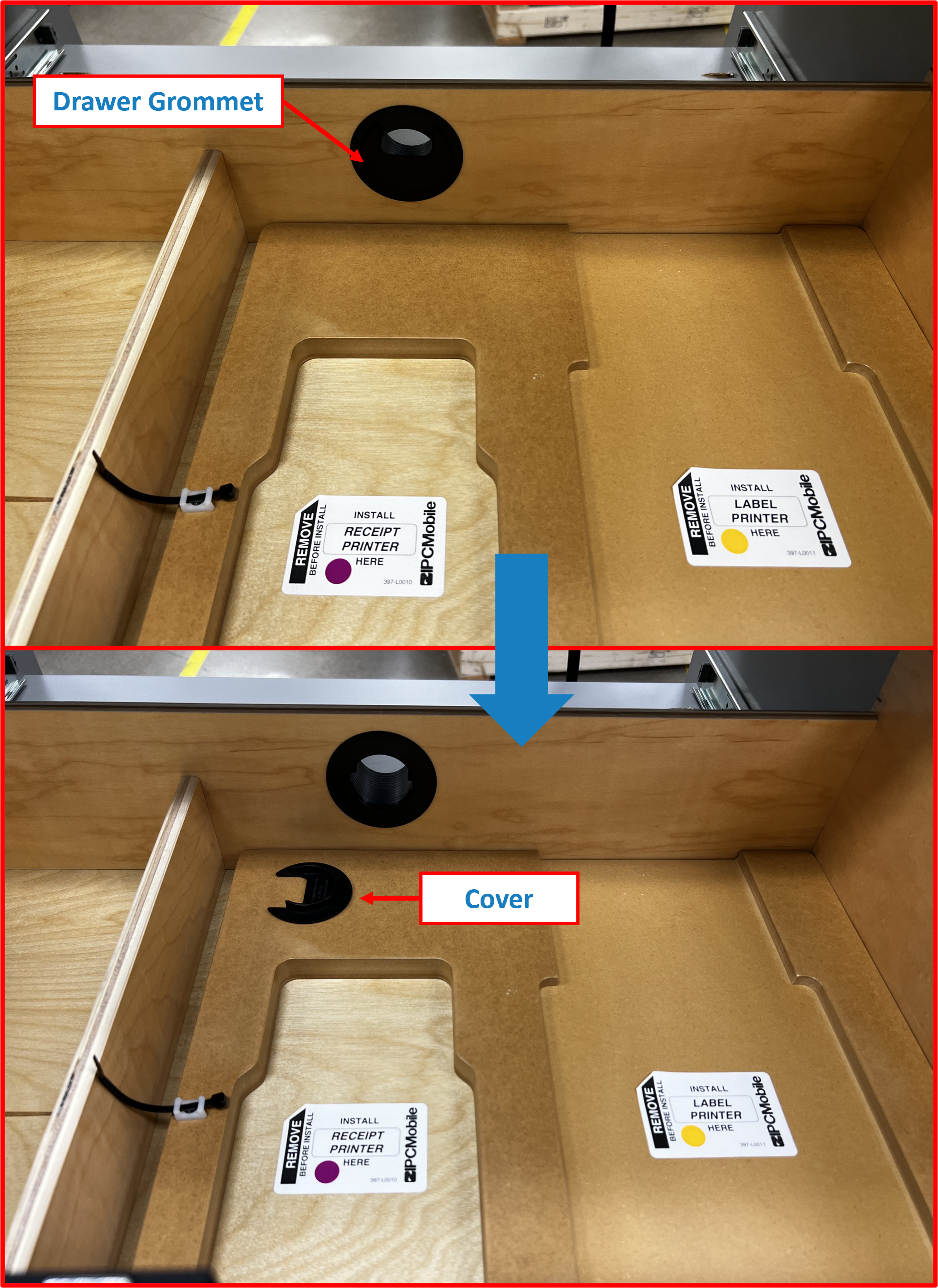
- Remove the
coverof theDrawer Grommet(pre-installed) from withinDrawerof theDESK.
Figure E2.14
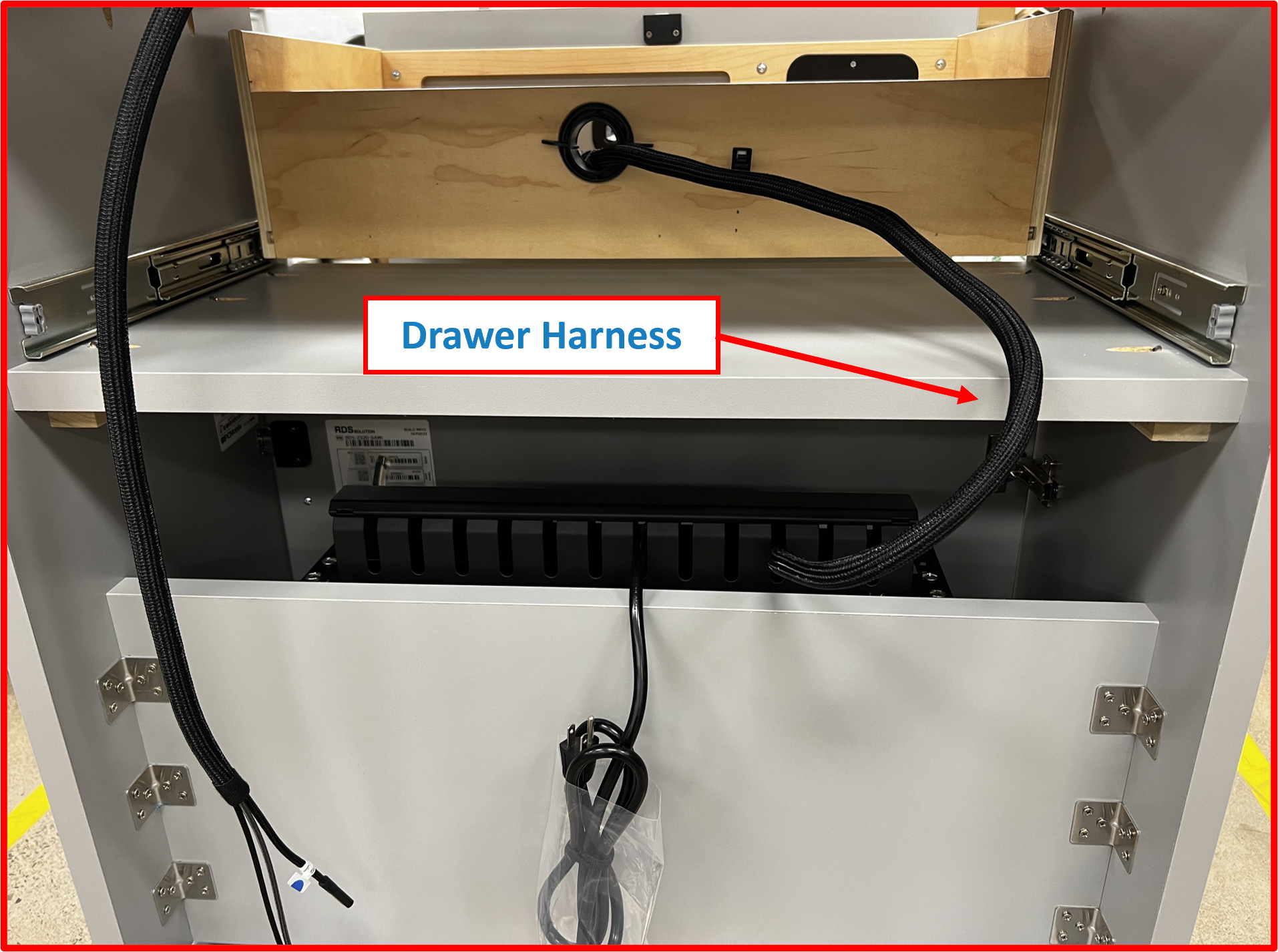
- From the backside of the Desk route
Drawer Harnessthrough theDrawer Grommet.
Figure E2.15
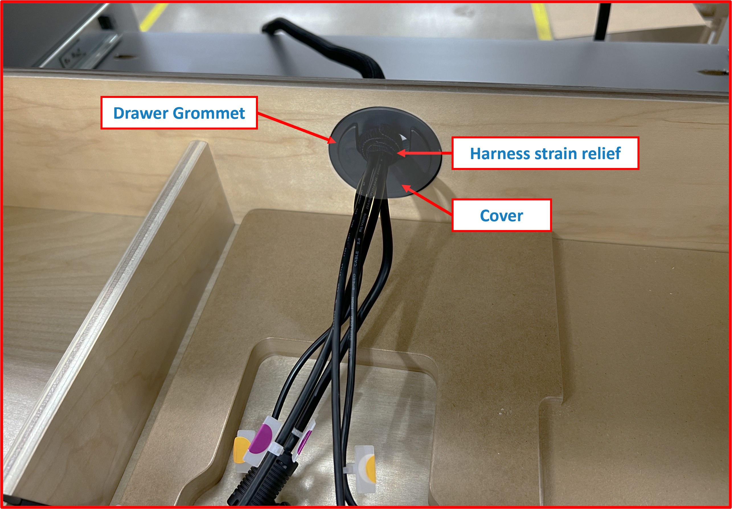
- Secure the
Drawer Harnessby reinstalling thecoverof theDrawer Grommet. Take care to ensure the harness strain-relief (pre-installed) is located inside the drawer area and resting against the the Grommetcoveras this will set the appropriate slack in the harness.
Figure E2.16
- Latch the
harness clampto lock in theDrawer Harness.
Figure E2.17
⚠️ WARNING
Test to make sure thereDrawer Harnesshas adequate slack and does not kink or bind by opening and closingDrawerfully.
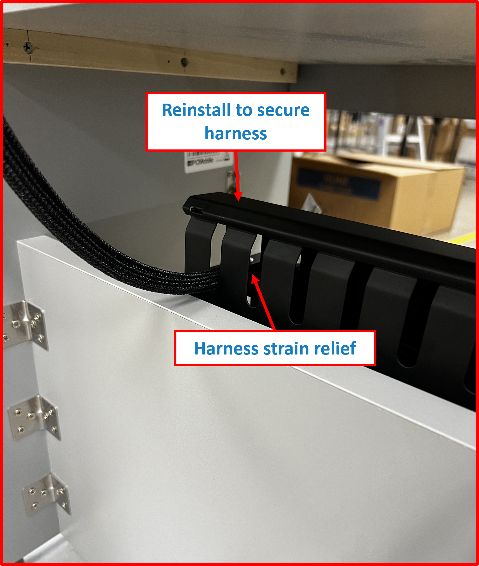
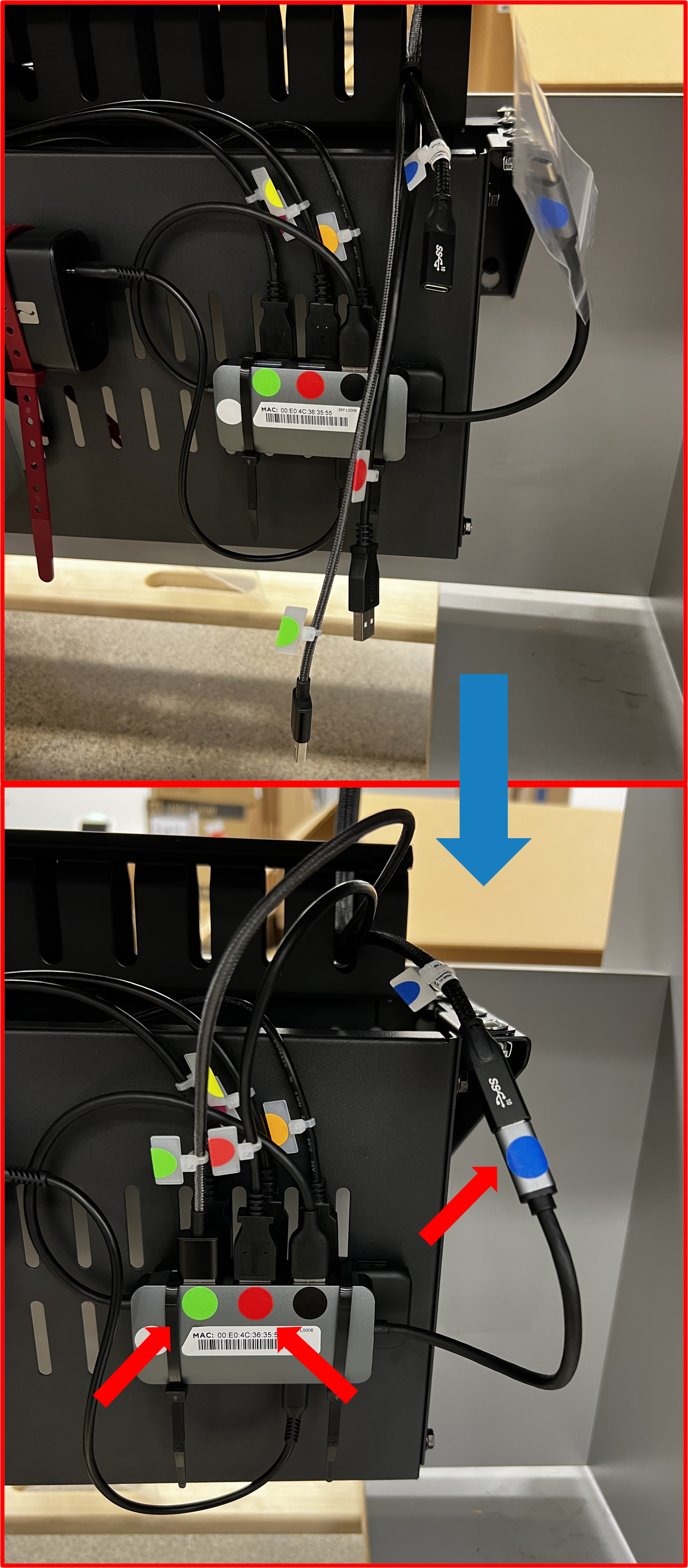
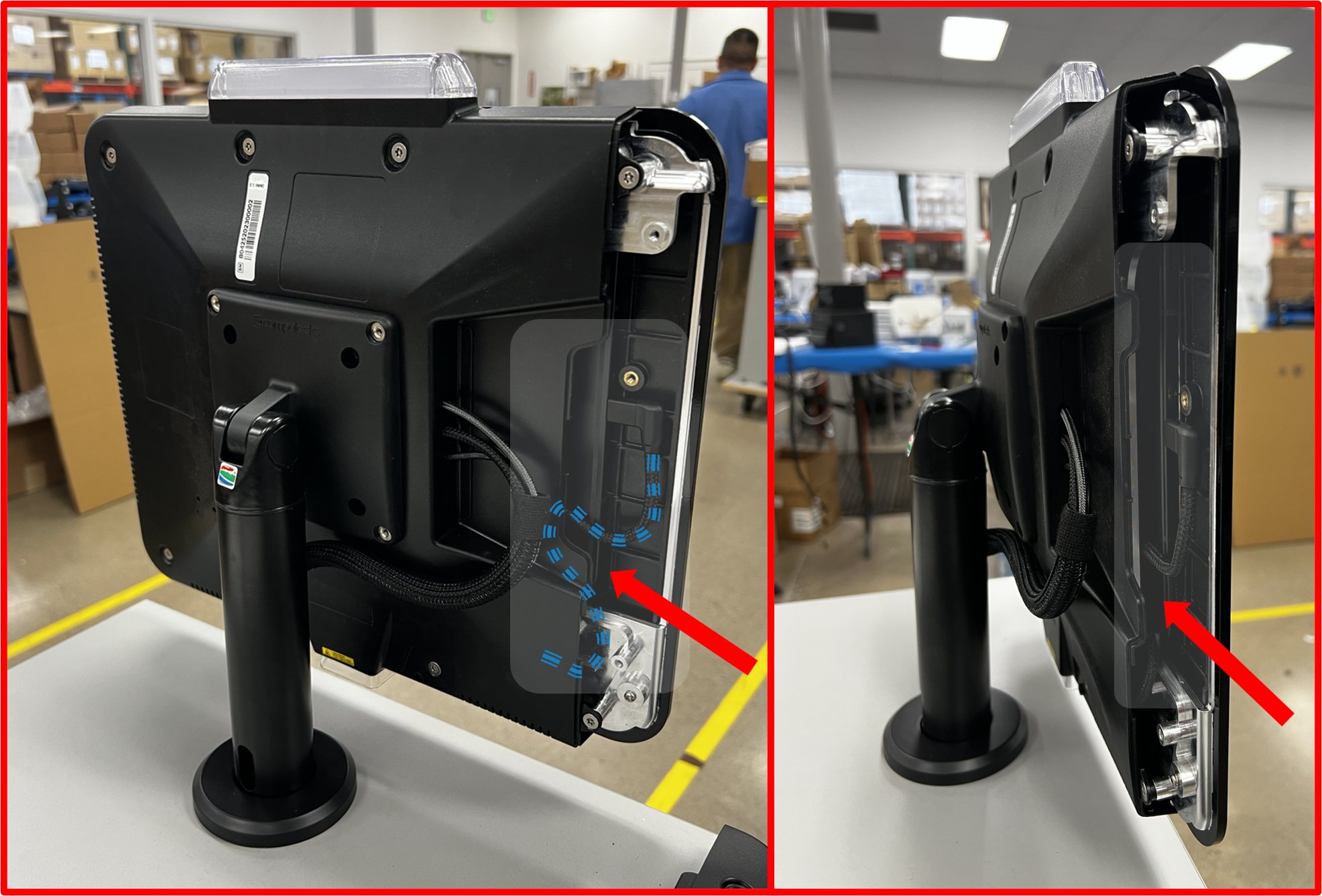
Step 5 | Connect OMNI Harness to SUB-SYSTEM
- Remove
coverofFinger Duct bracket.
Figure E2.18
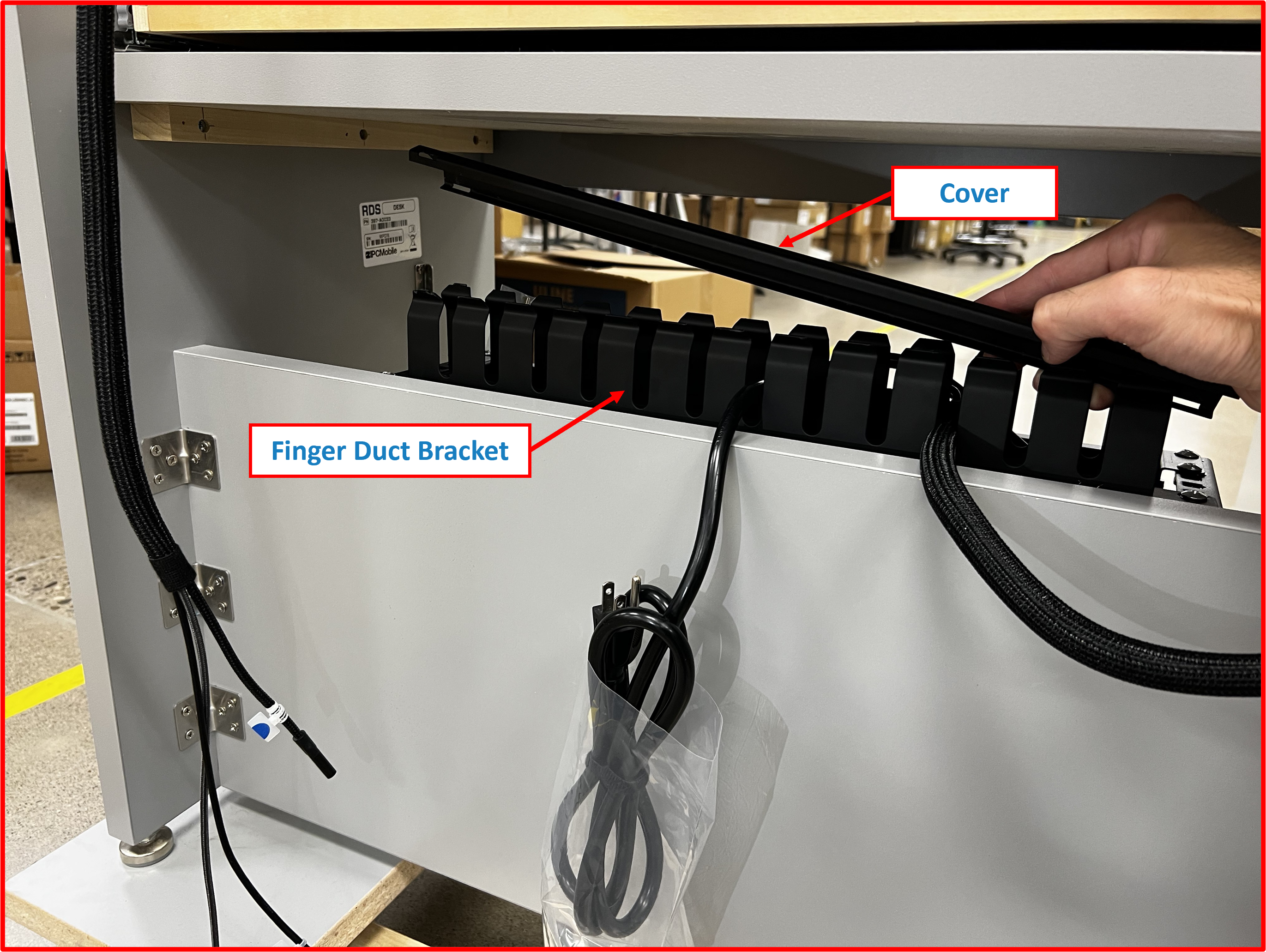
- Route
OMNI harnessas shown in designated slot. Take care to install strain relief of harness within theFinger Duct bracketto help retain proper slack.
Figure E2.19
- Reinstall finger duct
coverto secure end of harness.
Figure E2.20
- From inside the service comparment, connect the
OMNI Harnessto theSUB-SYSTEMby plugging in the appropriate color coded connections.
Figure E2.21
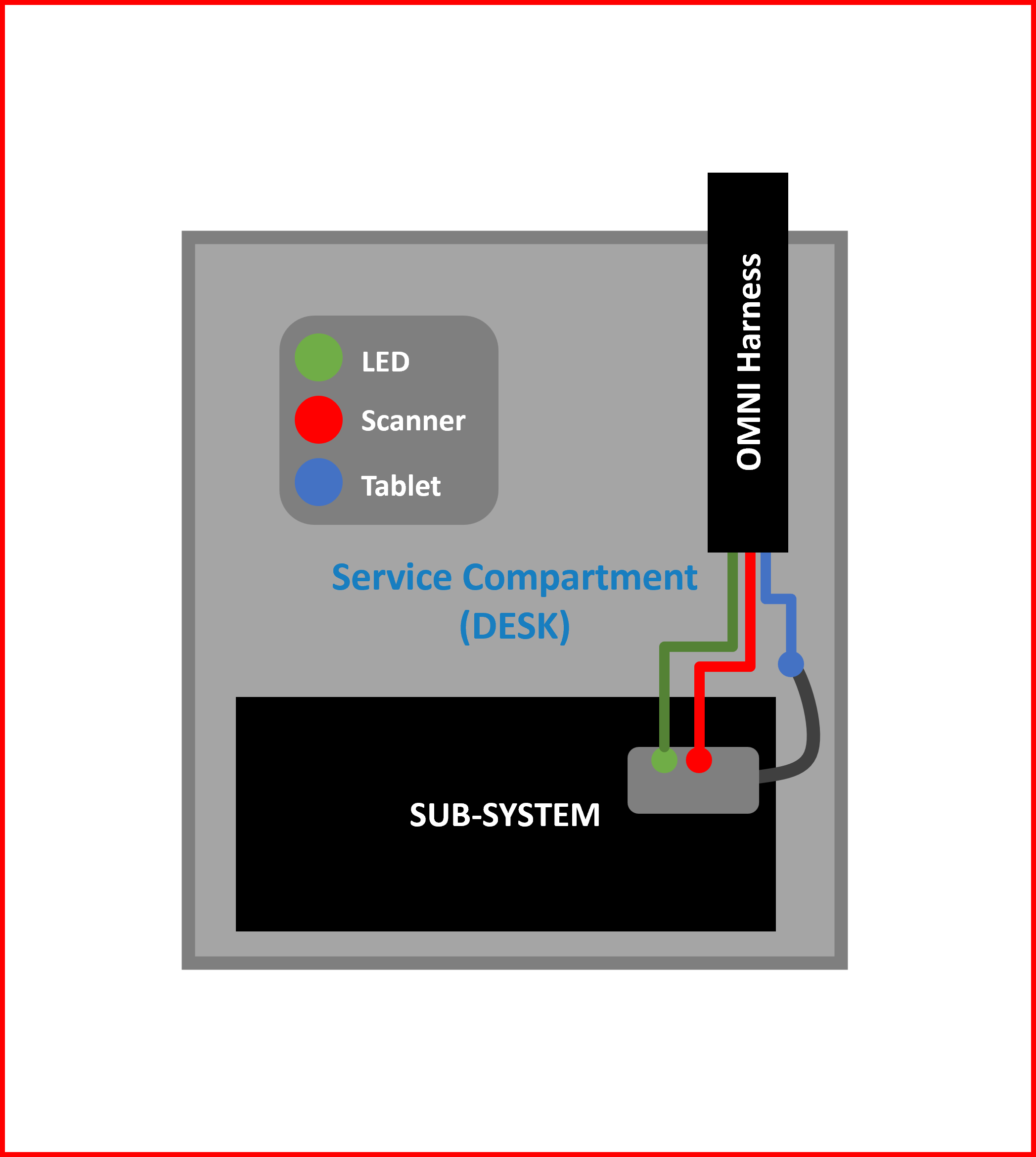
Figure E2.22
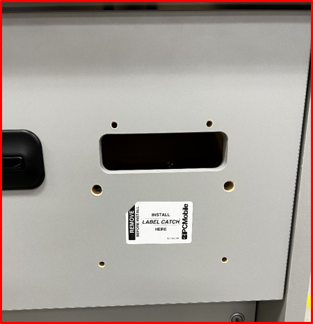
Step 6 | Install Label Catch
- Note install location for
Label Catchon outside face of theDrawer. Remove temporary label.
Figure E2.23
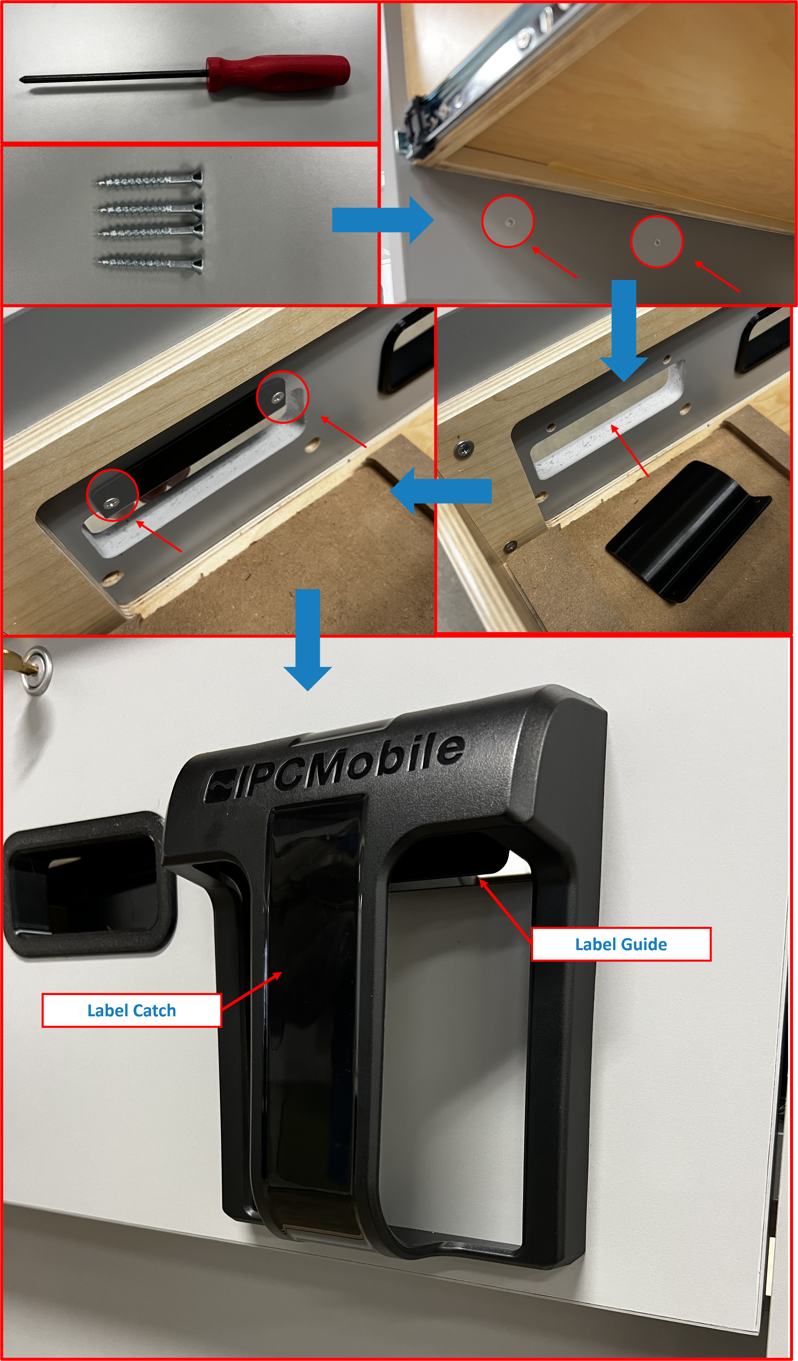
- Using supplied hardware (SEE BOX 3) and
screwdriver, installLabel CatchandLabel Guide.
ℹ️ NOTE
- Take care to orientate as shown for proper installation.
- Recommend installing the bottom 2 screws of the
Label Catchfirst to hold it in place. Then install top 2 screws to secure theLabel Guidefrom inside theDrawer.- Remove any protective film at this time.
Figure E2.24
Step 7 | Install Printers
ℹ️ NOTE
Remove if any and all plastics pre-installed into Receipt slot opening on Drawer face. These will be replaced by the flexibleGrommetsupplied inBOX 9(optional).
- Install
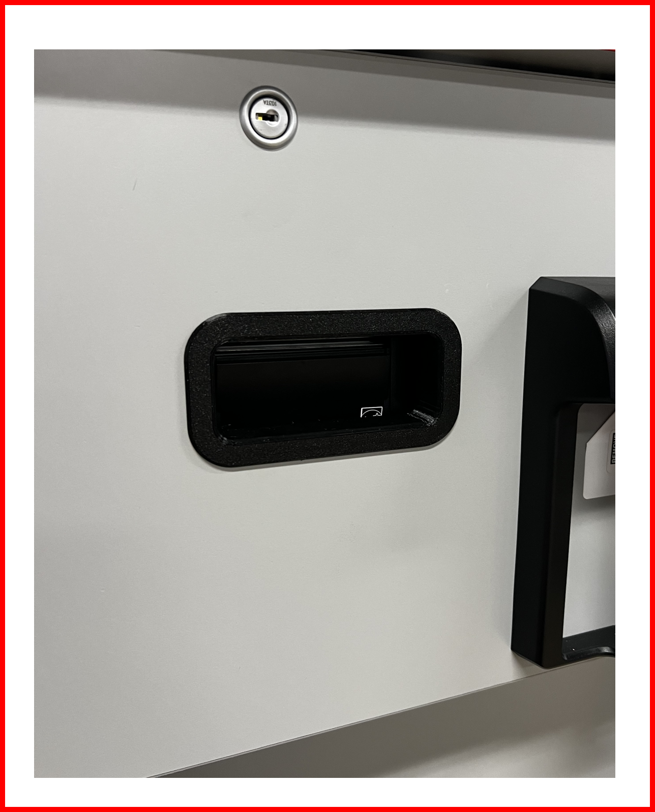
Grommetinto receipt slot opening on Drawer face with textured side face out as shown.
Figure E2.25
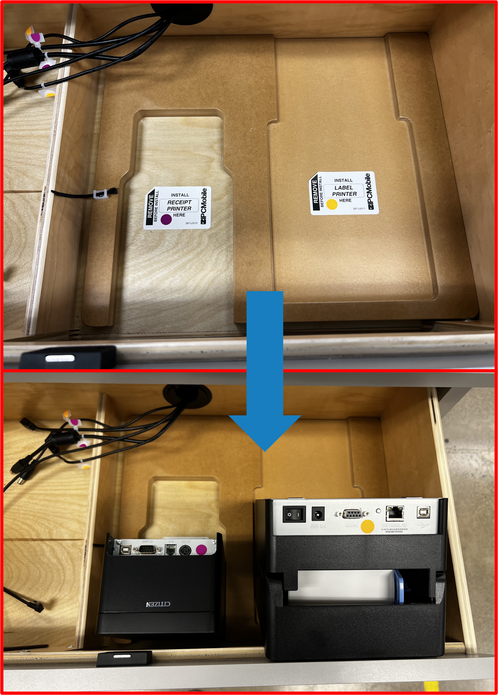
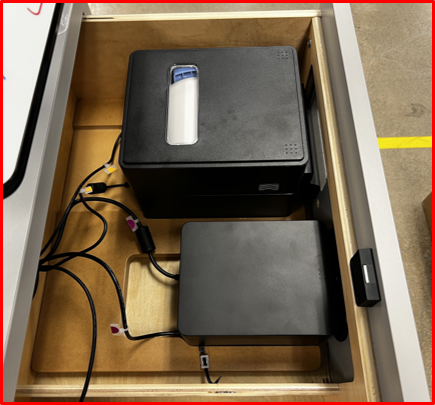
- Note install location for
Label PrinterandReceipt PrinterinsideDrawerarea and labeled connections. SetPrintersinto approximate locations face down in order to access rear connections.
Figure E2.26
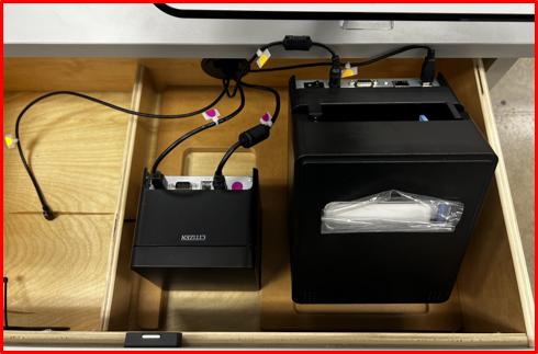
- Connect Power and Data connection for
Label PrinterandReceipt Printeras labeled.
Figure E2.27
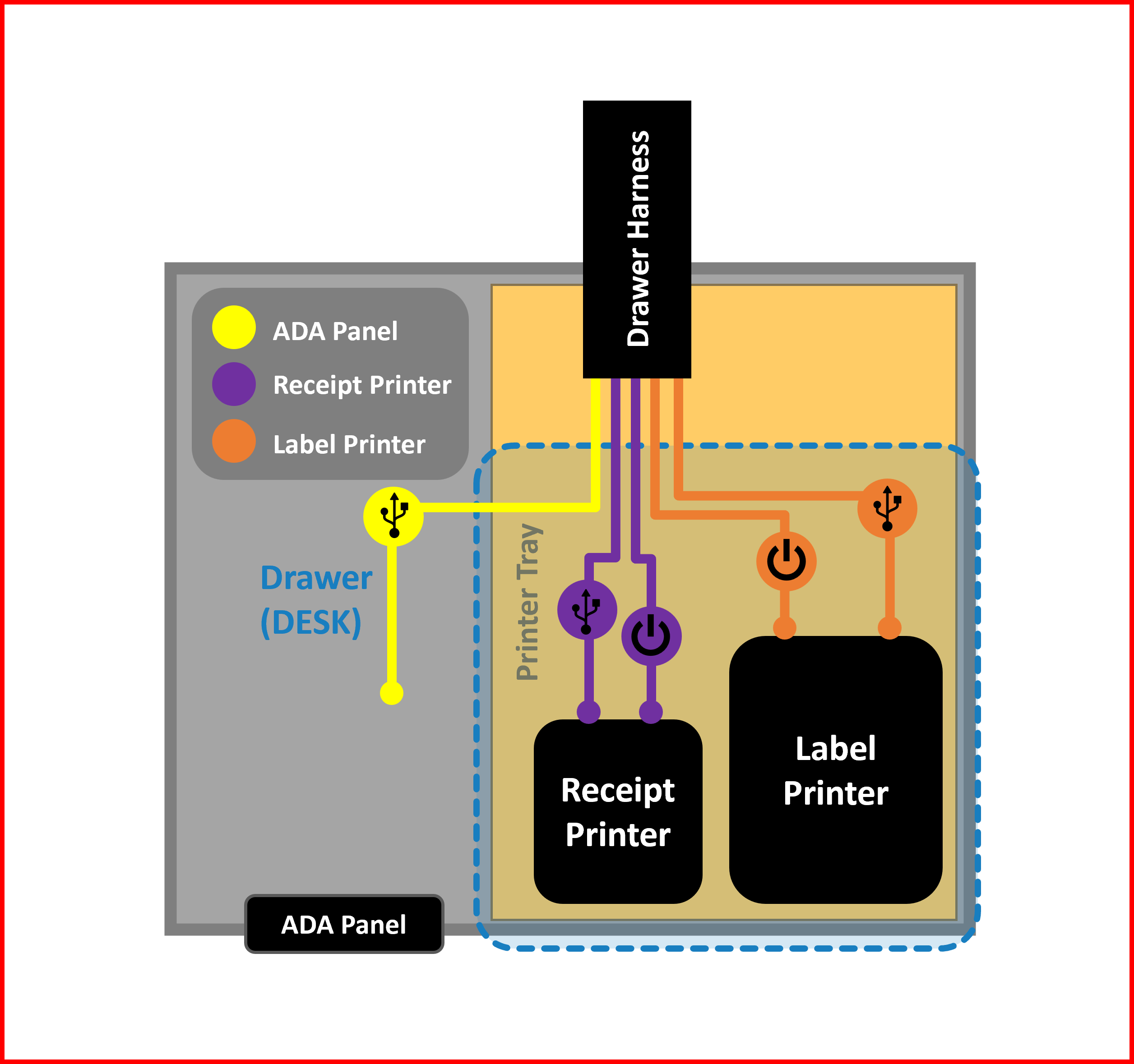
Figure E2.28
- Re-orientate
Printersinto final installation position by "dropping" them into appropriate pockets inside theDrawer.
Figure E2.29
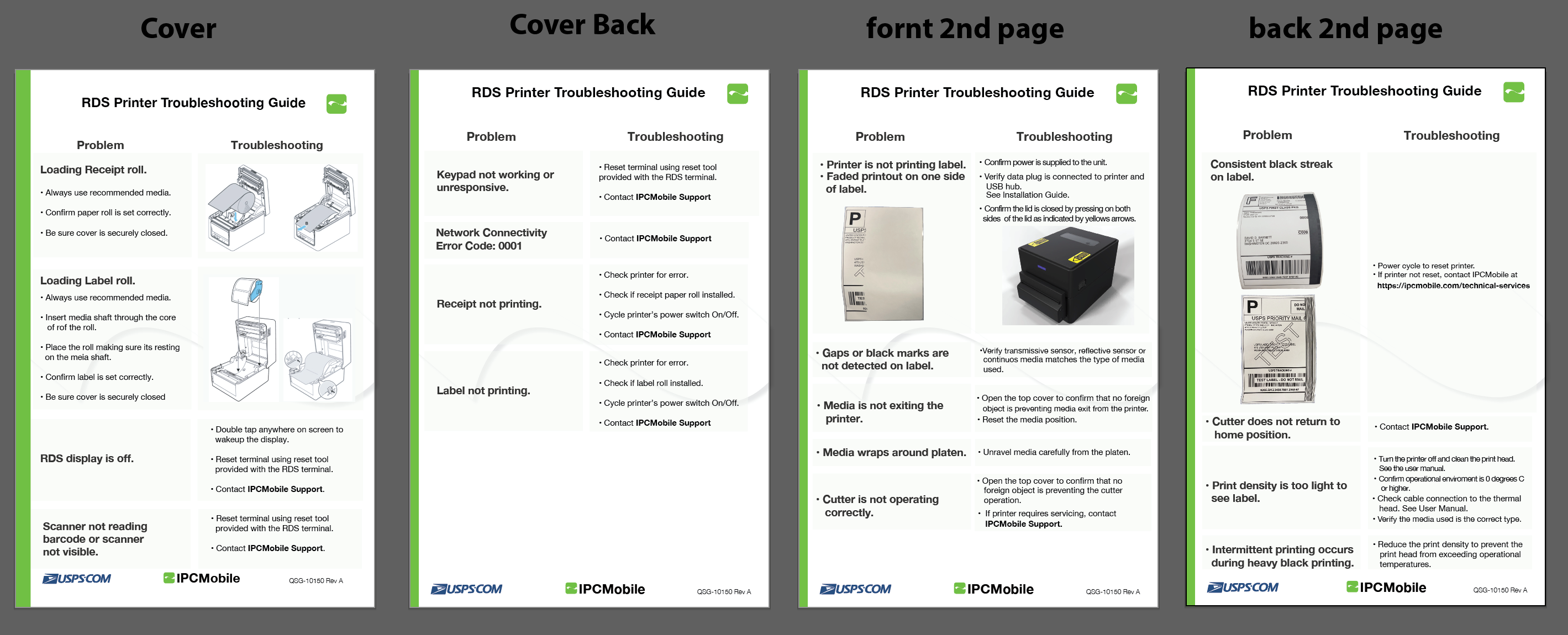
⚠️ WARNING
Take care to ensure printer media is properly installed (SEE RDS Printer Troubleshooting Guide) andPrintersare seated flat against the base of theDrawerfor proper function.
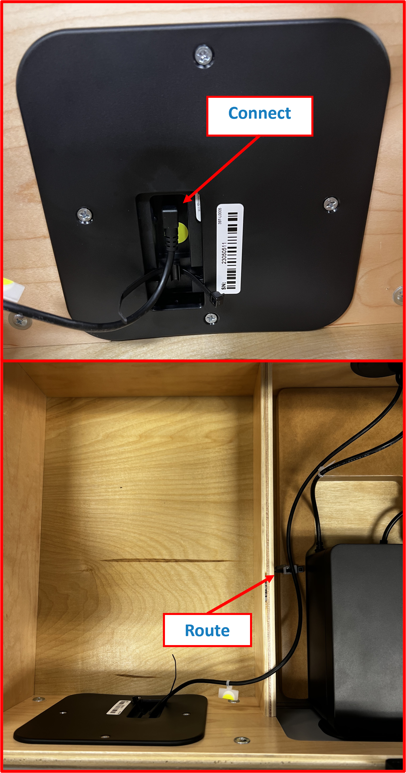
Step 8 | Install ADA Panel
- Using supplied
Front Bezel,Rear Bezeland hardwarescrewsfromBOX 9, InstallADA panelintoDrawerface with marked data connection port located inside and orientated as shown.
Figure E2.30
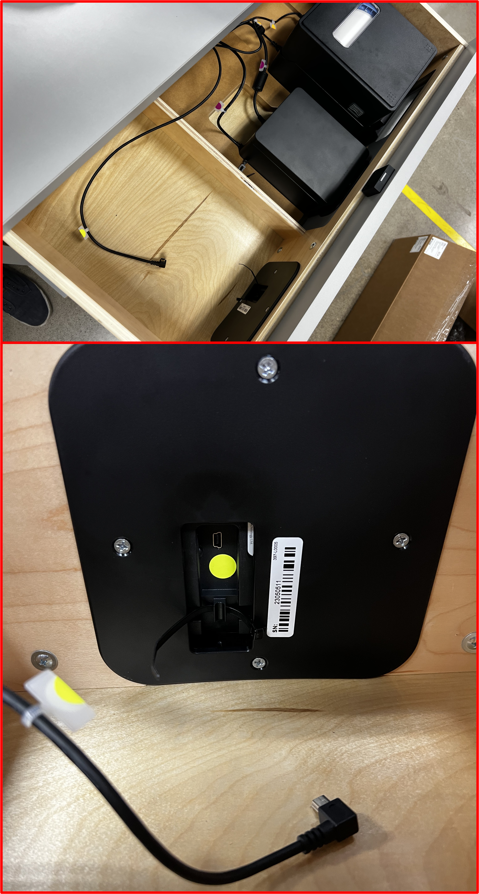
- Route appropriate data cable as shown and connect to
ADA panel.
Figure E2.31
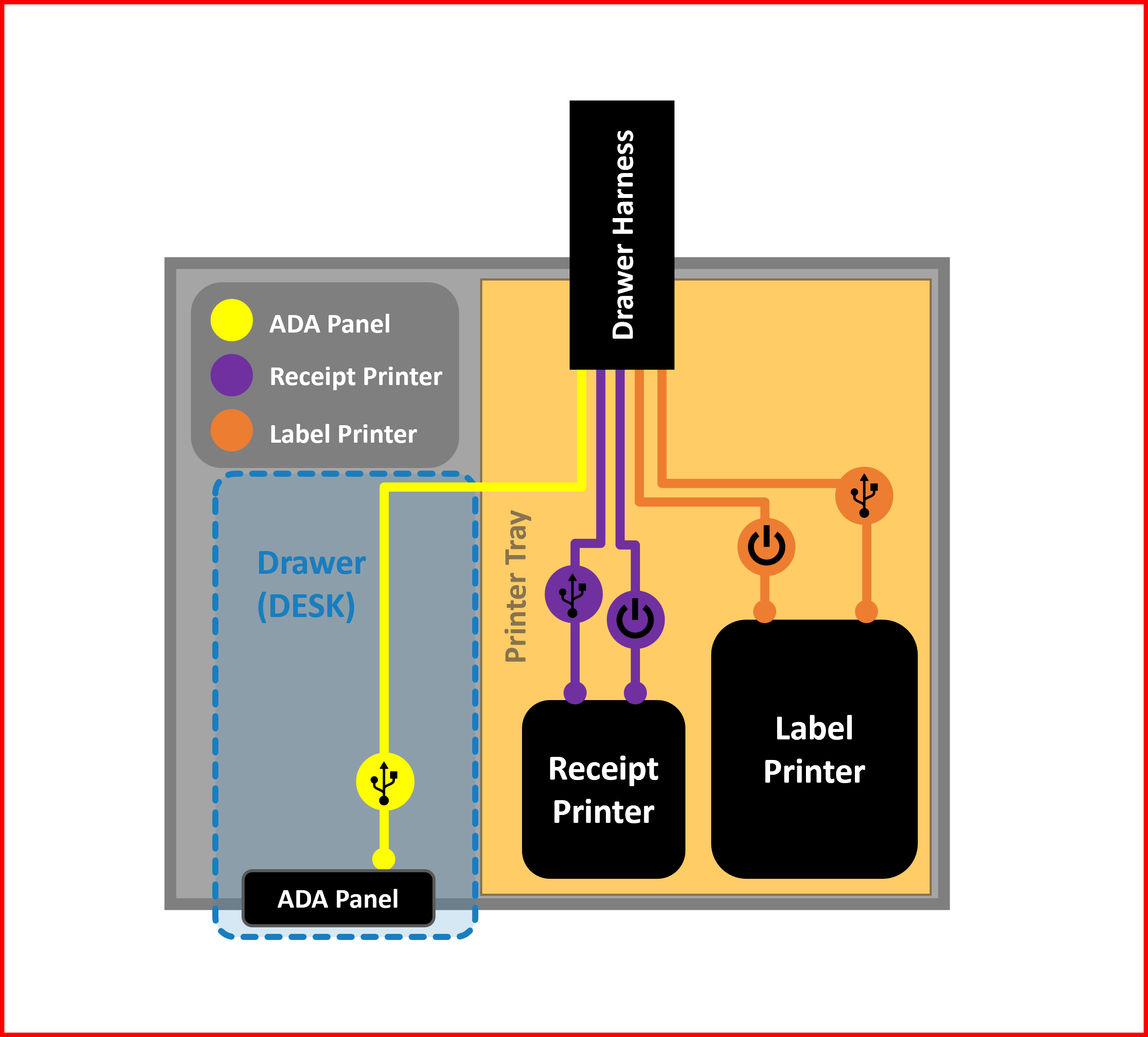
Figure E2.32
- Tighten zipties (pre-installed) to secure cable.
Figure E2.33
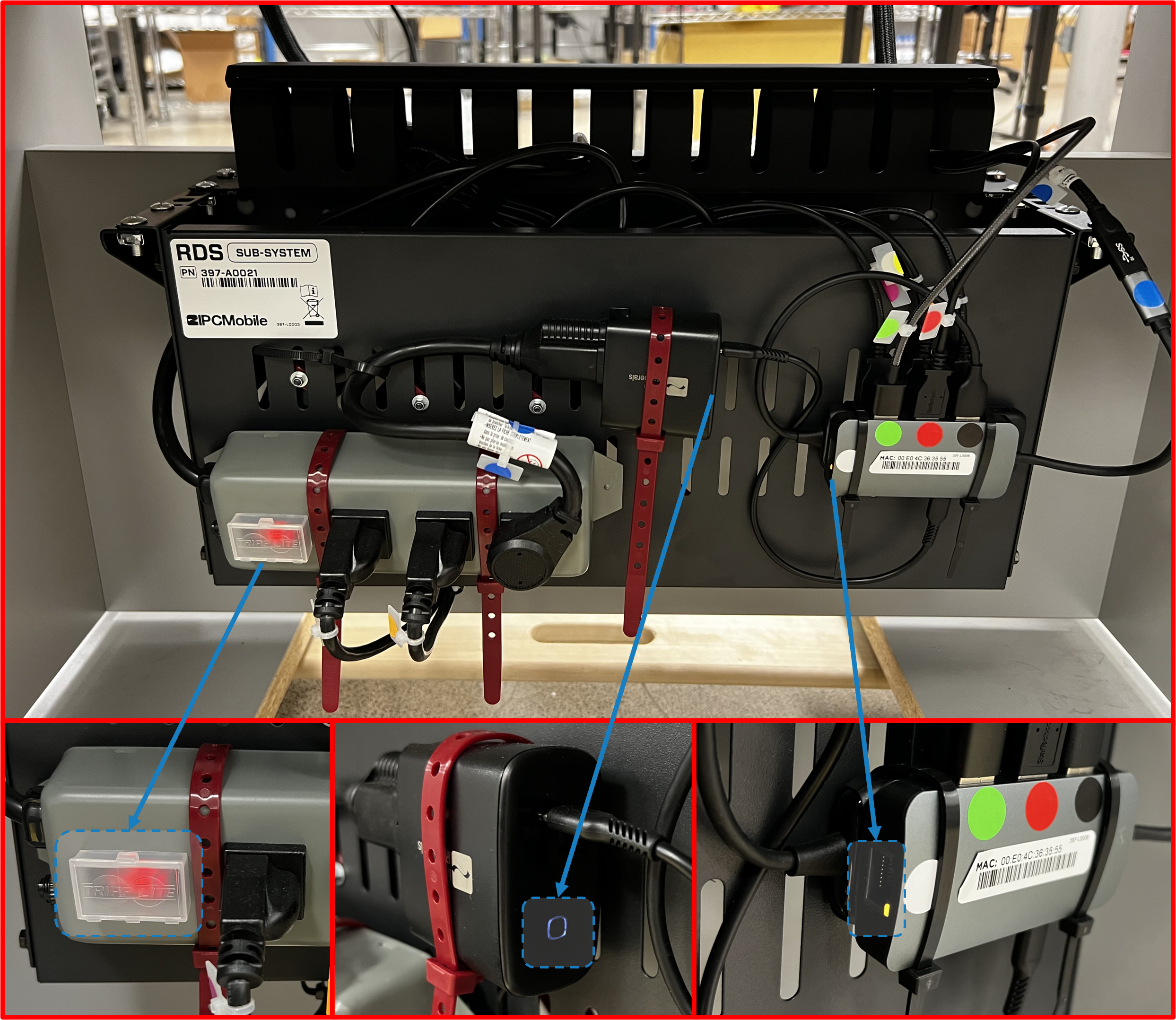
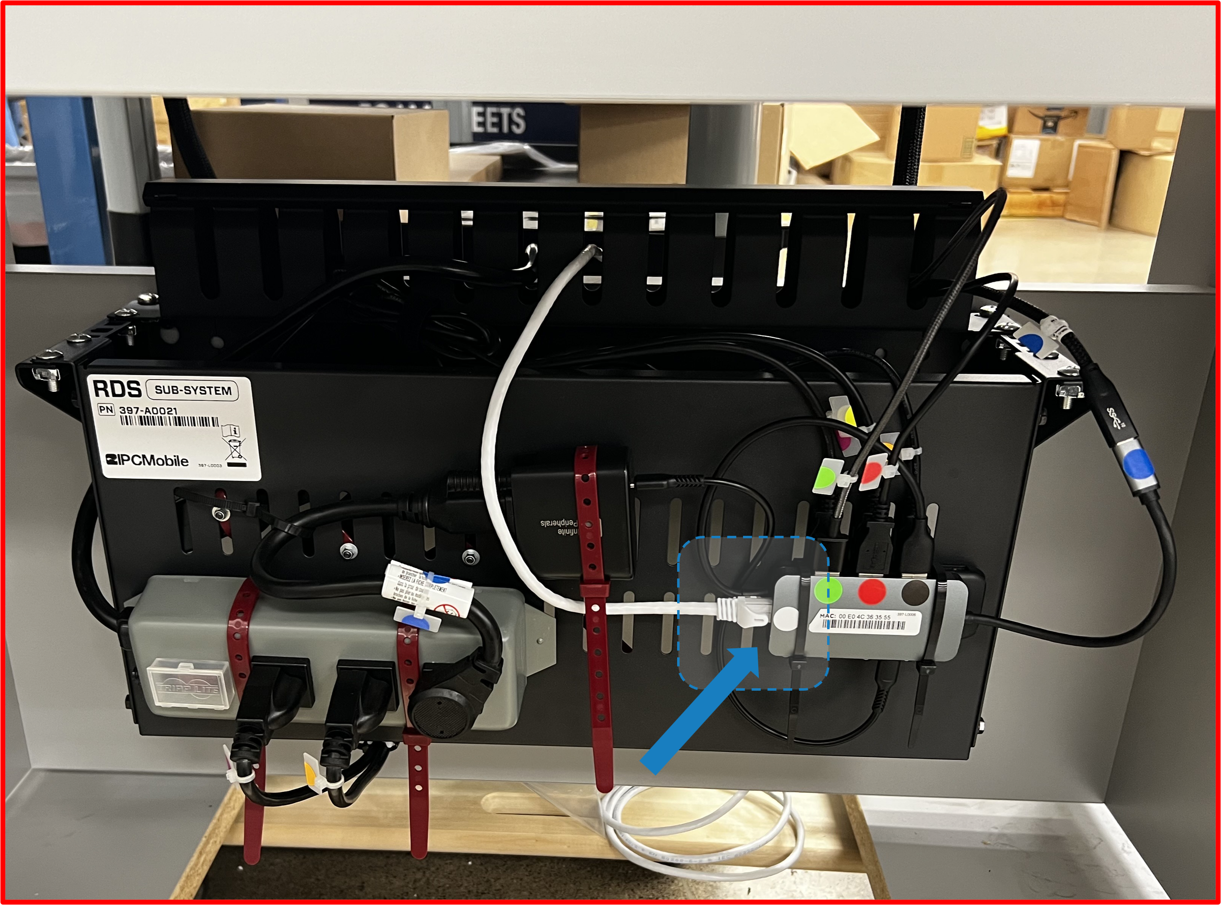
Step 9 | Connect System to Power
- Connect
Power Cordto AC power outlet.
Figure E2.34
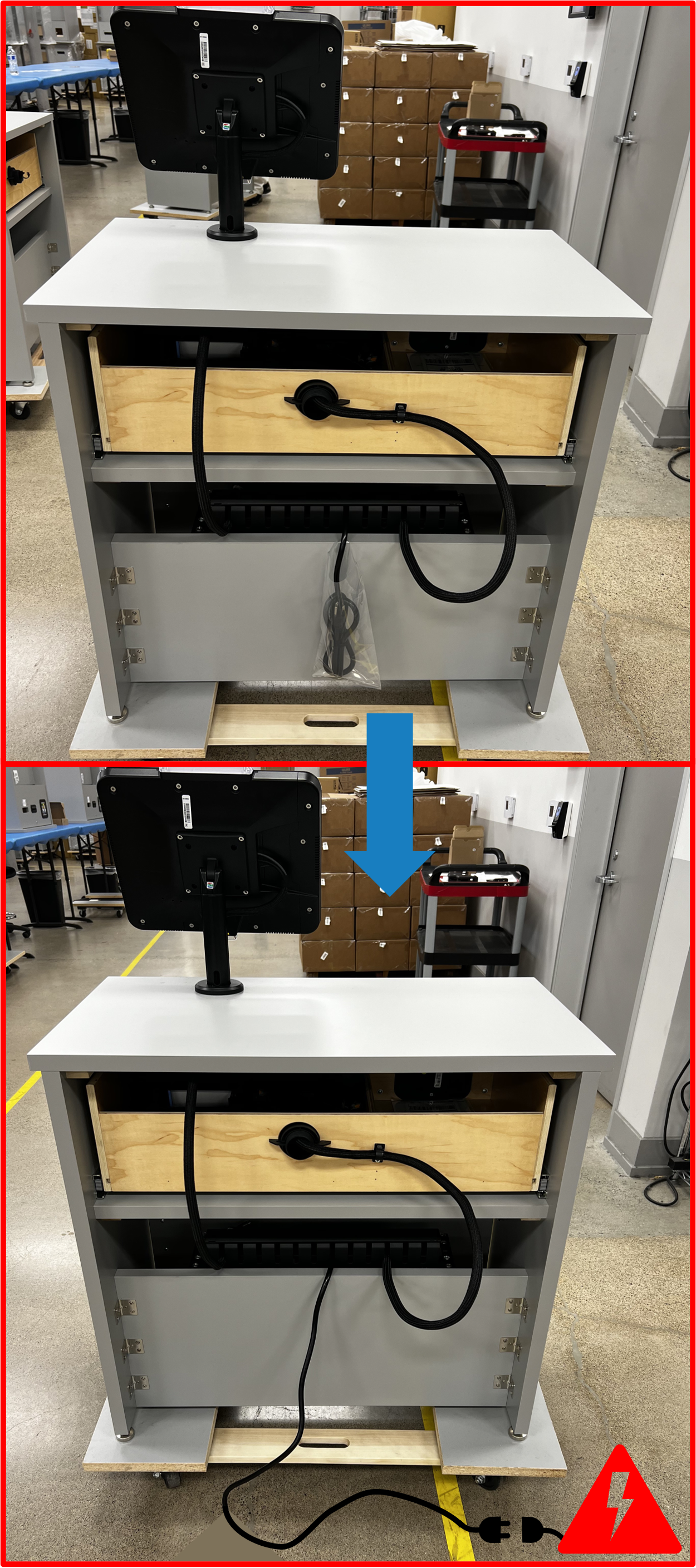
ℹ️ NOTE
To confirm the System has Power, please verify all of the following (SEESUB-SYSTEMinService CompartmentofDESK):
- Orange LED on the Power Switch of the Power Strip is lit up.
- White LED on the USB-C Power Adapter is lit up.
- Yellow LED on Ethernet Port of USB-C Hub (labeled with White Dot) is lit up.
Figure E2.35
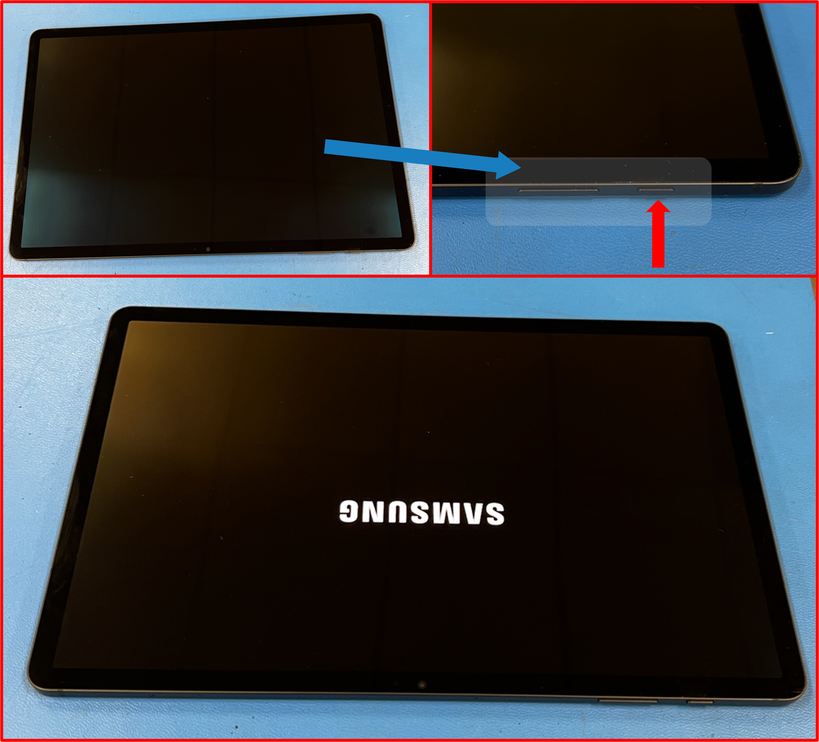
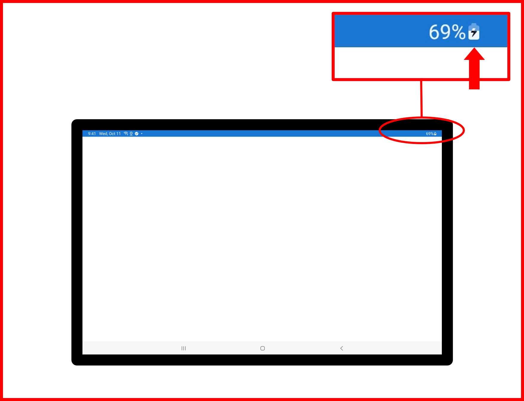
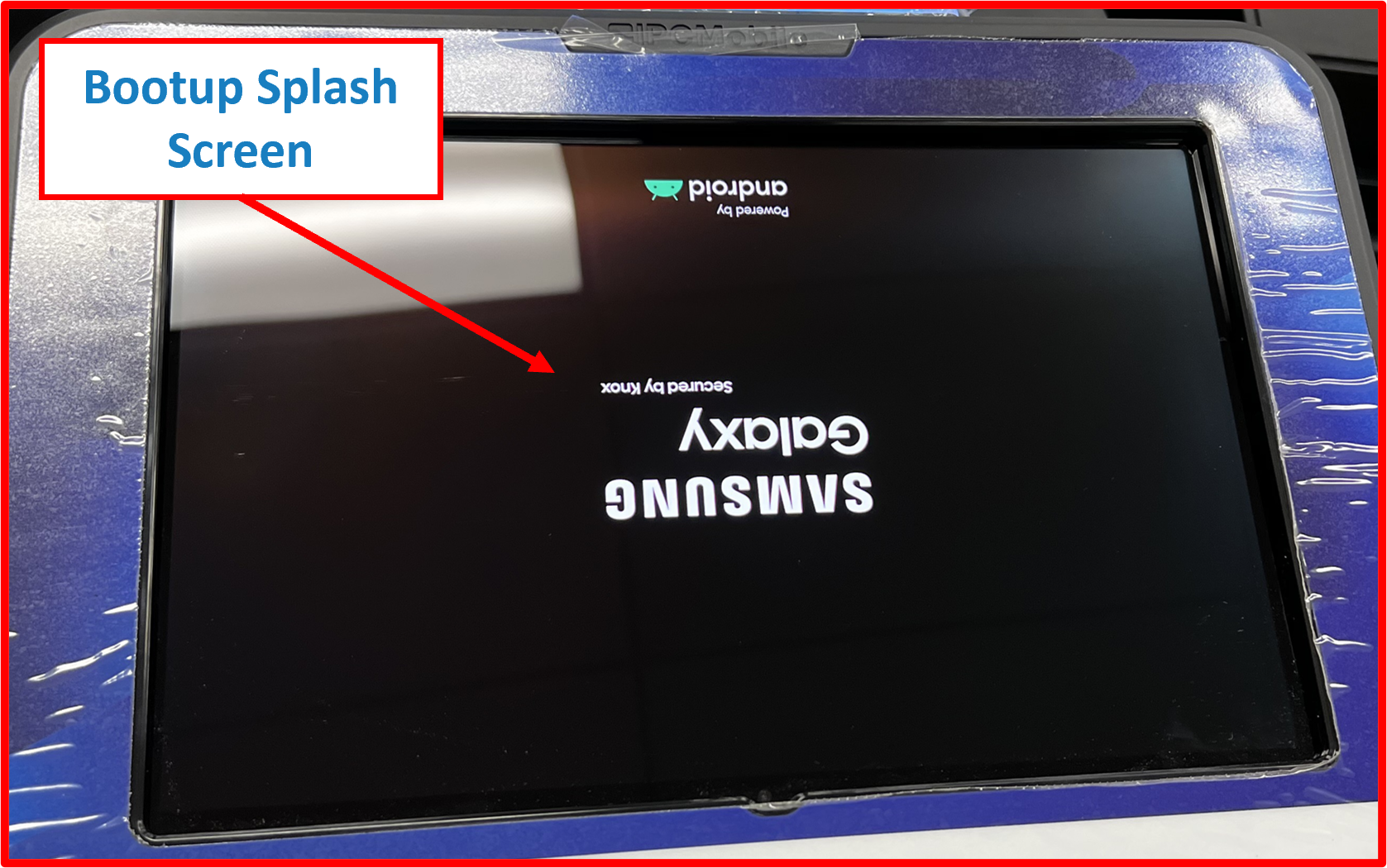
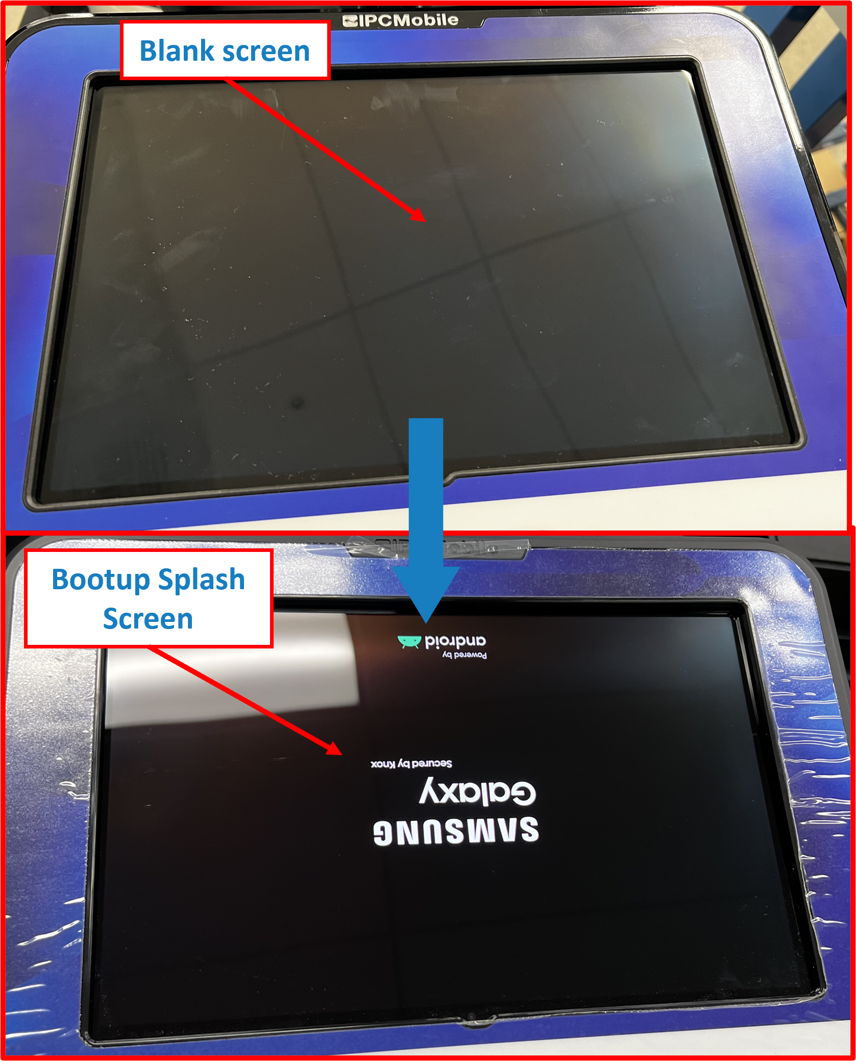
Step 10 | Power ON Tablet
- Hold POWER button for 5 seconds to Power ON
Tablet. Samsung splash screen should appear to signifyTabletis booting up.
Figure E2.36
ℹ️ NOTE
- In the event that
Tabletwill not Power ON, then most likely the battery has died andTabletwill need to be charged.- Please skip ahead to Step 11 as installing the
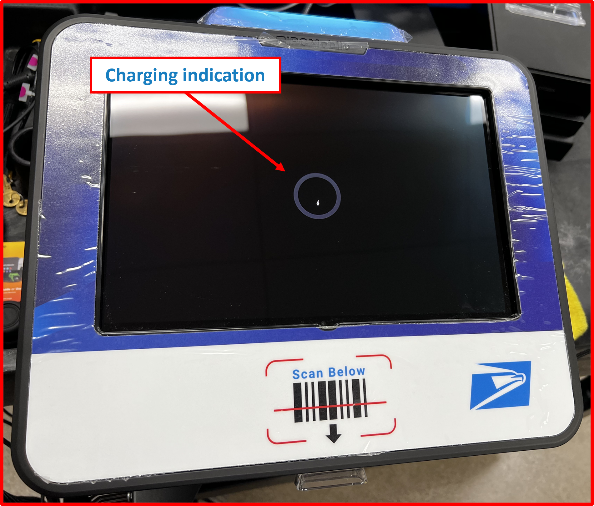
Tabletinto theOMNIwill charge the Tablet.- Let the
Tabletsit for at least 15 MIN before attempting to Power ON theTabletagain from within the enclosure. Once USB-C cable is connected Step 11.5Tabletwill begin charging immediately and screen should indicate charging state as shown. This screen will timeout within 15 seconds of being connected though and the screen will turn OFF despite active charging.
Figure E2.37
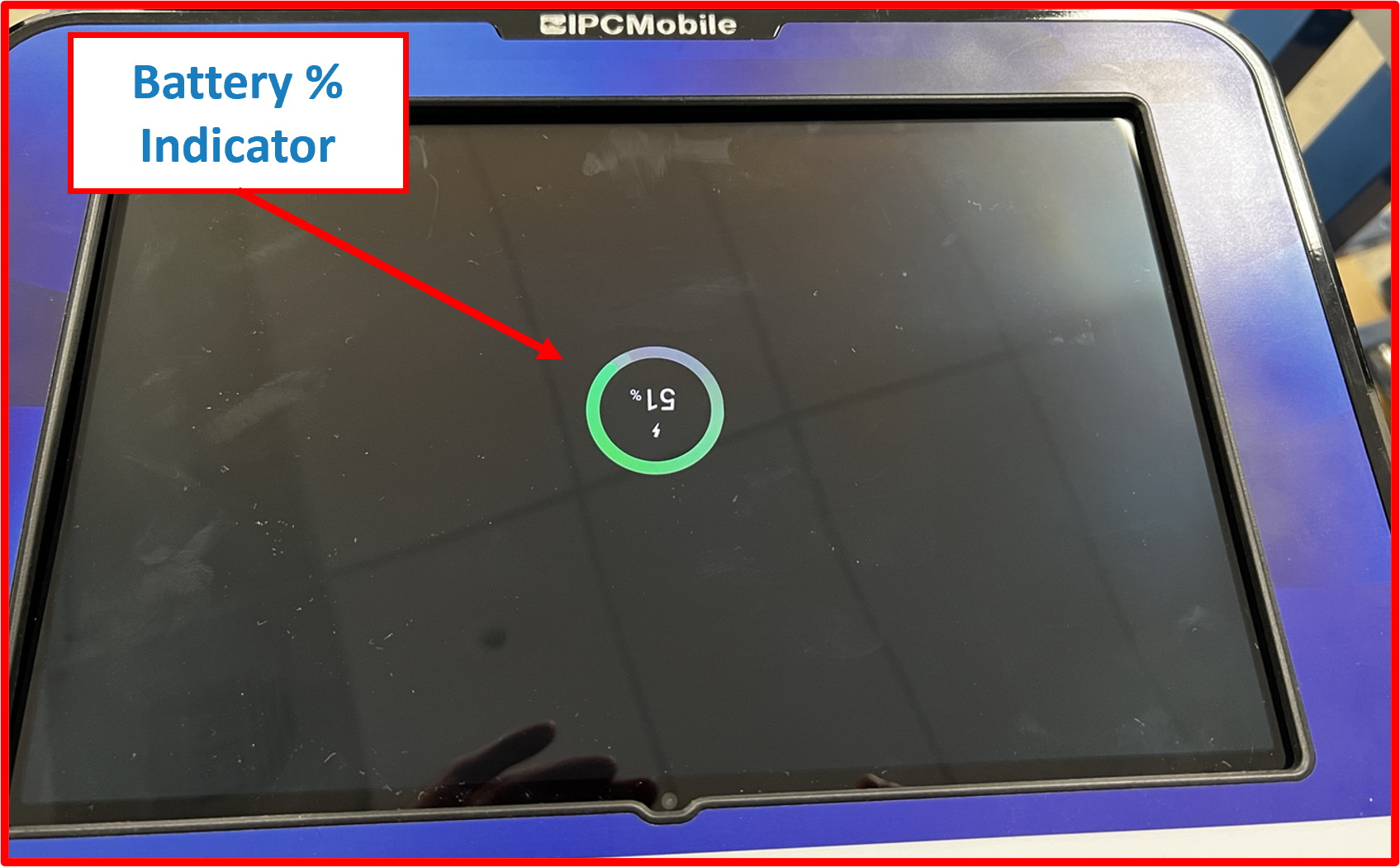
- To check battery status or ensure charging is indeed active, SEE Step 1 of Supplemental Step A and short-press
PIN TOOLin opening (less than 3 seconds). Screen should indicate charging state AND/OR battery percentage.
Icon on screen will appear upside down at this point. This is NORMAL.
Figure E2.38
- To Power ON the
Tabletafter it is installed intoOMNIenclosure SEE Supplemental Step A for proper procedure.
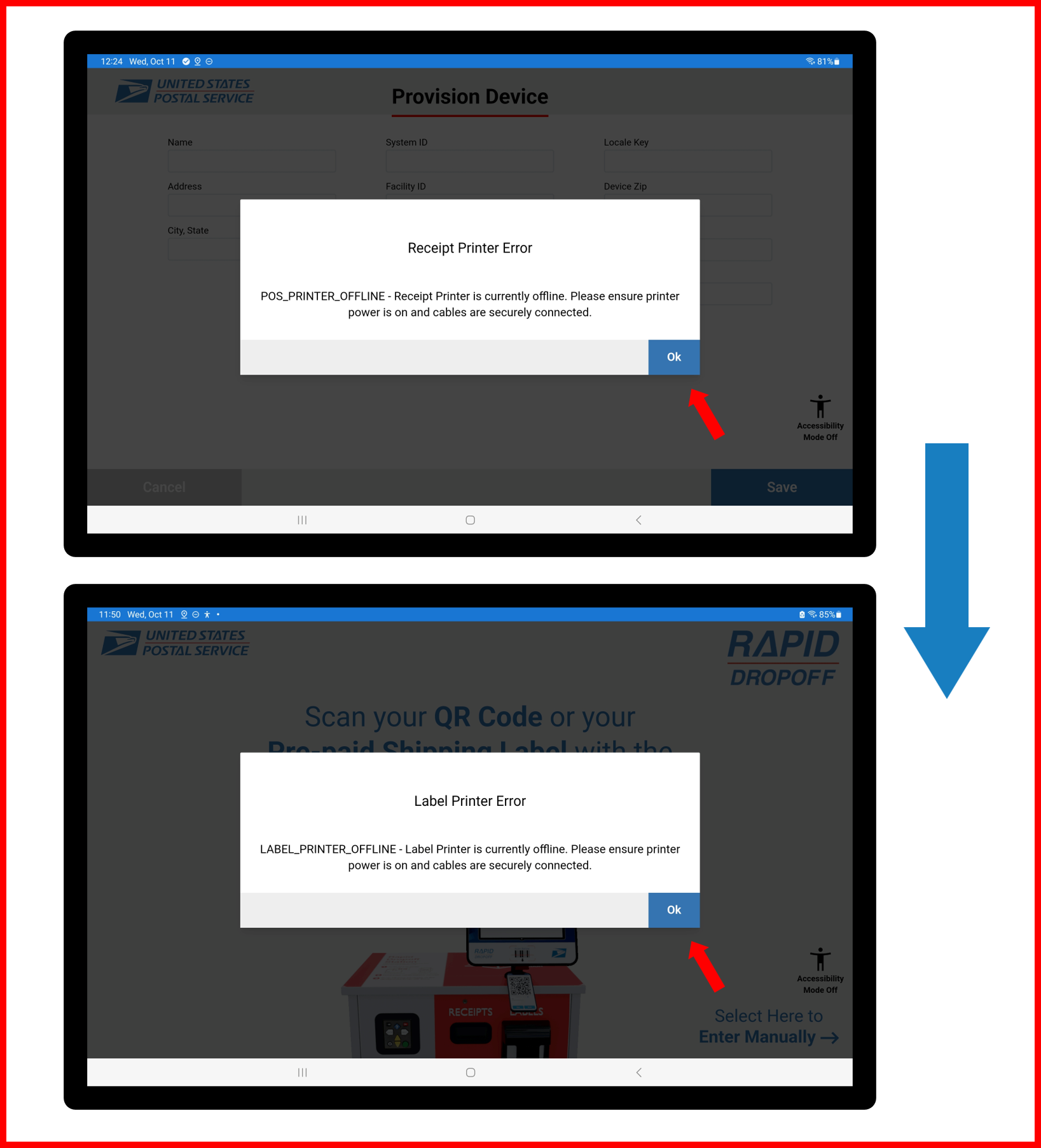
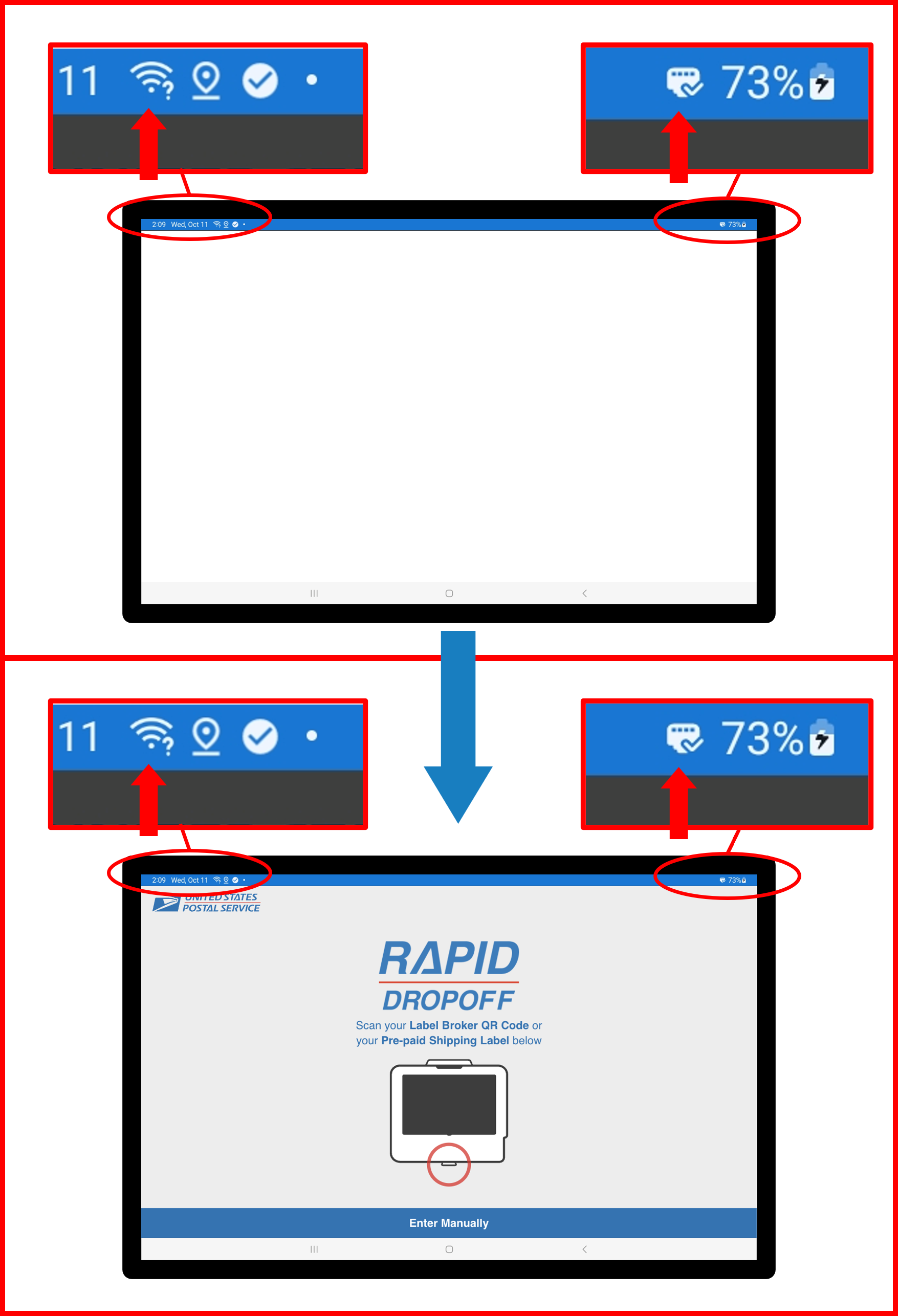
- Confirm network connectivity after Tablet finishes booting up.
❗ IMPORTANT
Ethernet connection will be REQUIRED --> skip ahead to Step 11 and subsequently SEE Step 12 for installing Ethernet cable.
- If screen appears blank, close and relaunch the application.
Figure E2.40
Figure E2.41
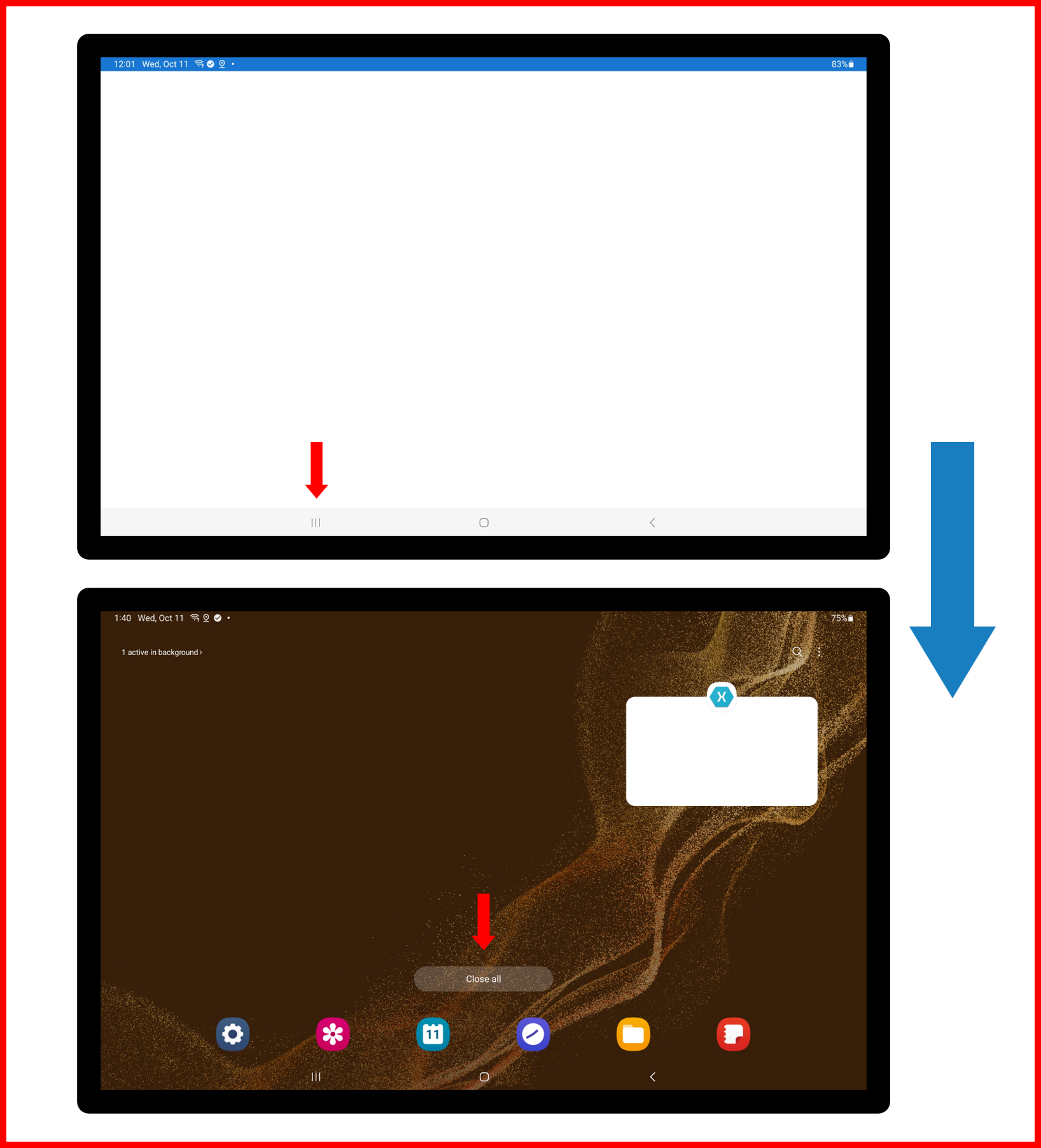
Figure E2.42
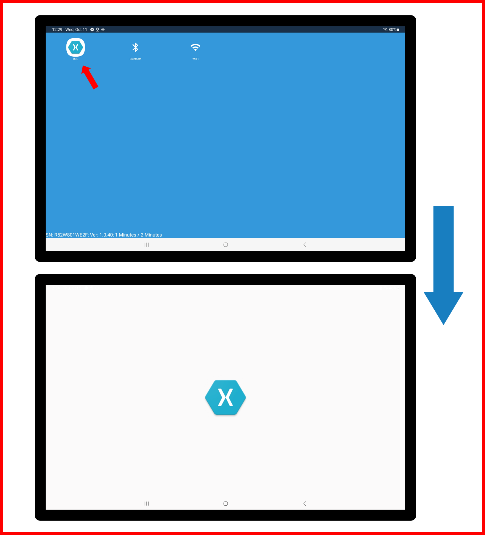
- If screen appears blue background, launch RDS application manually (as shown above).
- Clear any and all error notifications if they pop-up by selecting OK on on-screen prompts.
Figure E2.43
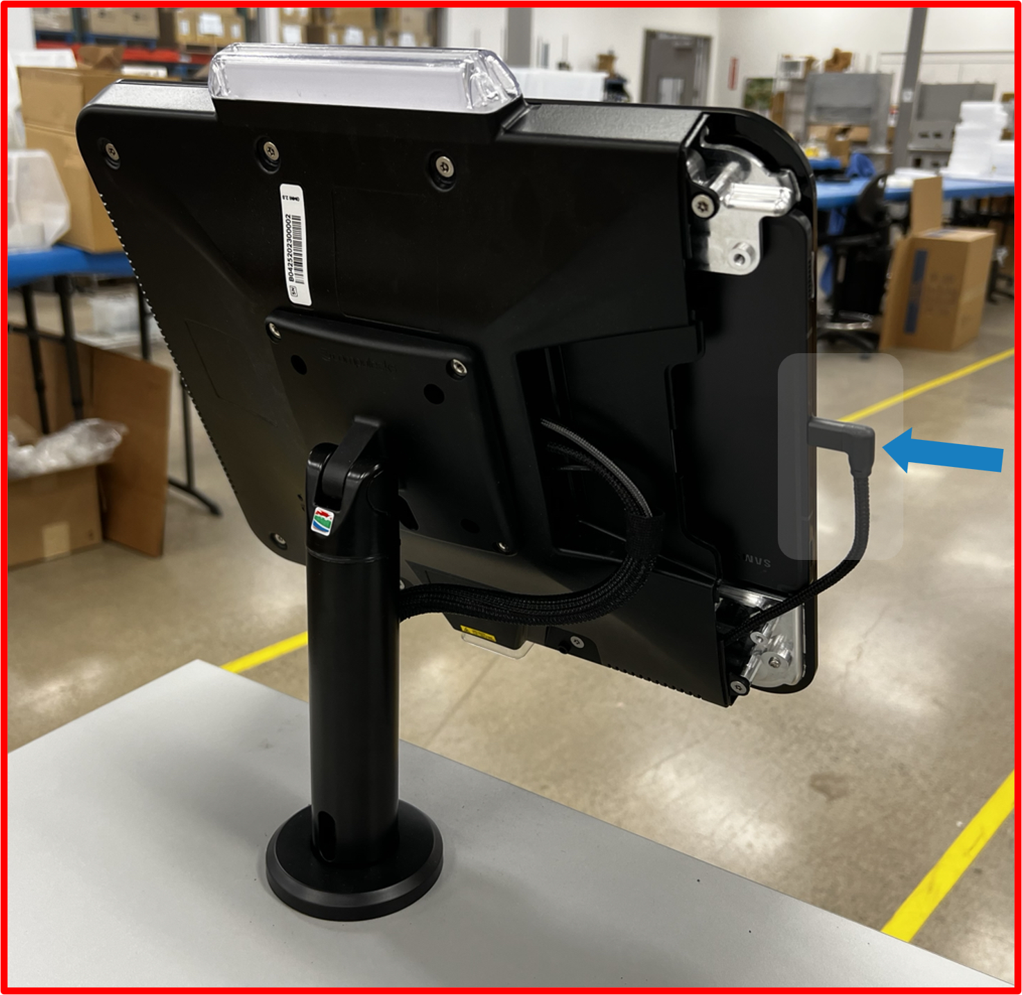
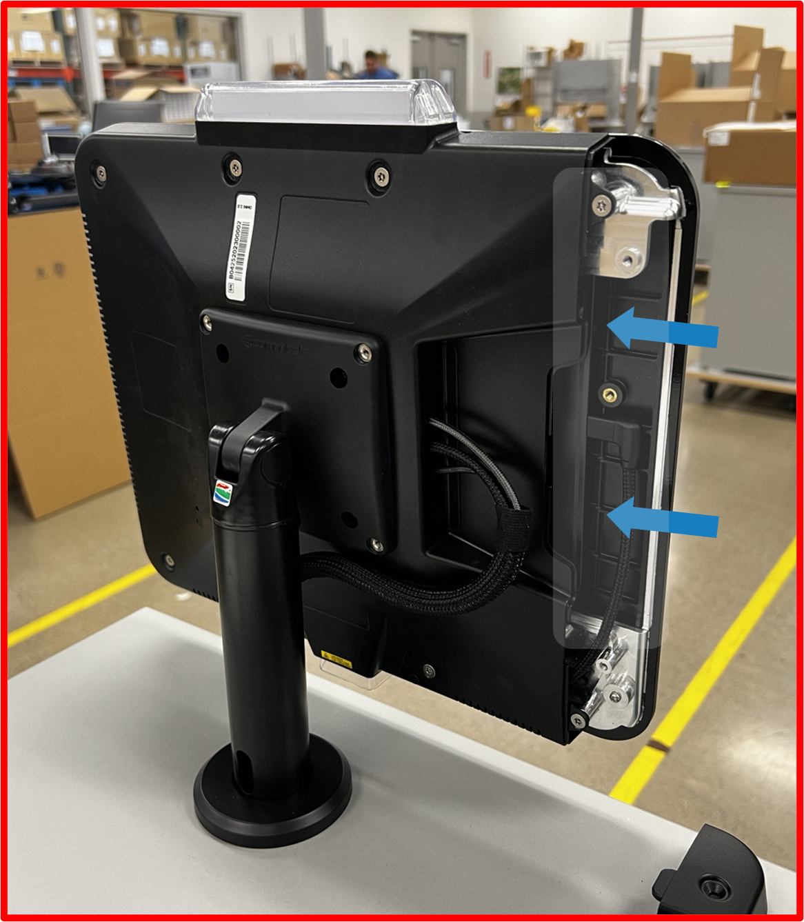
Step 11 | Install Tablet into OMNI
- Using supplied T20 allen key, remove 3
security screwsfrom OMNIside cover.
ℹ️ NOTE
Take note of screw lengths and their proper location. The middle screw is the longest.
Figure E2.44
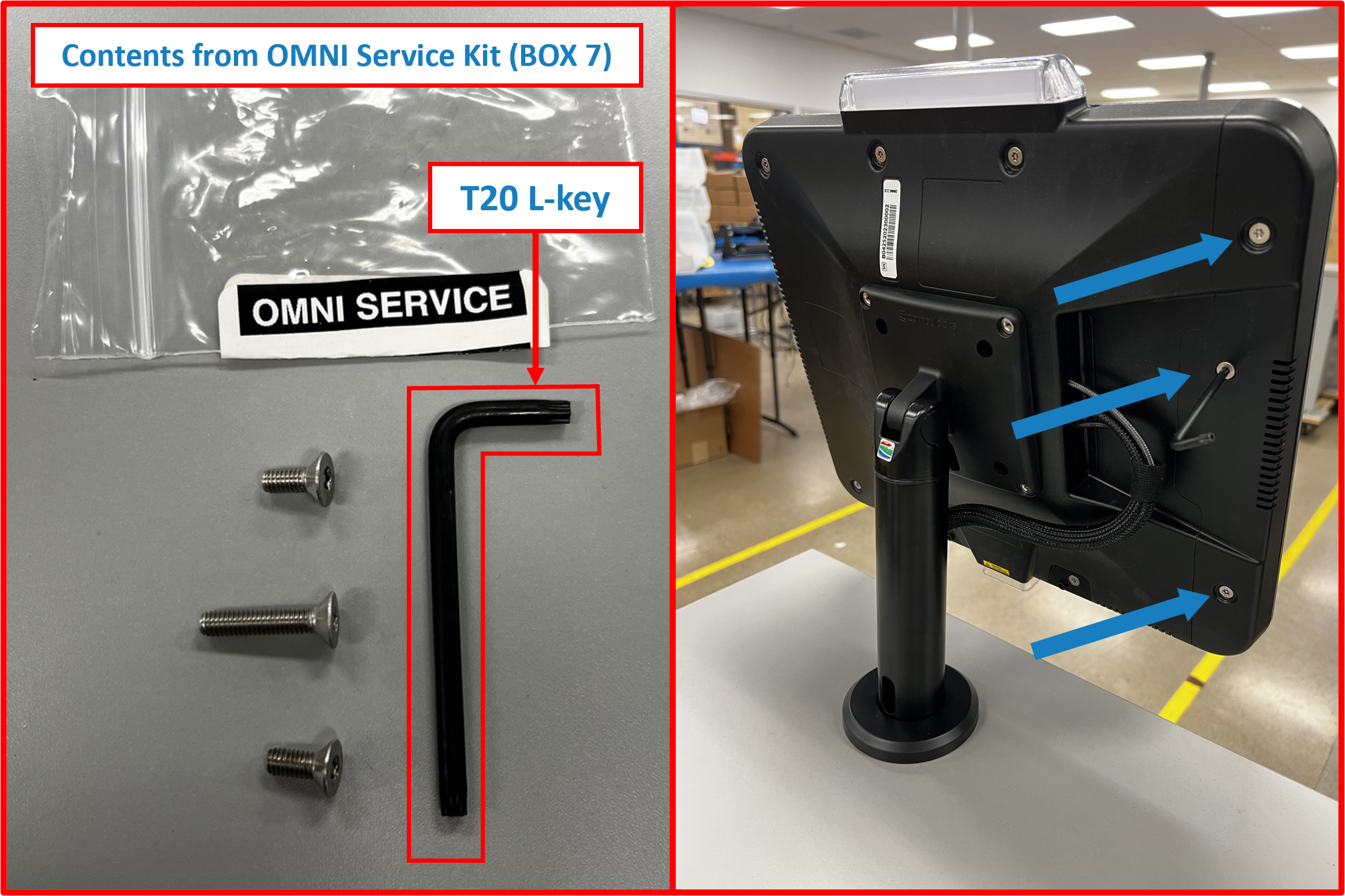
- Remove
side cover.
Figure E2.45
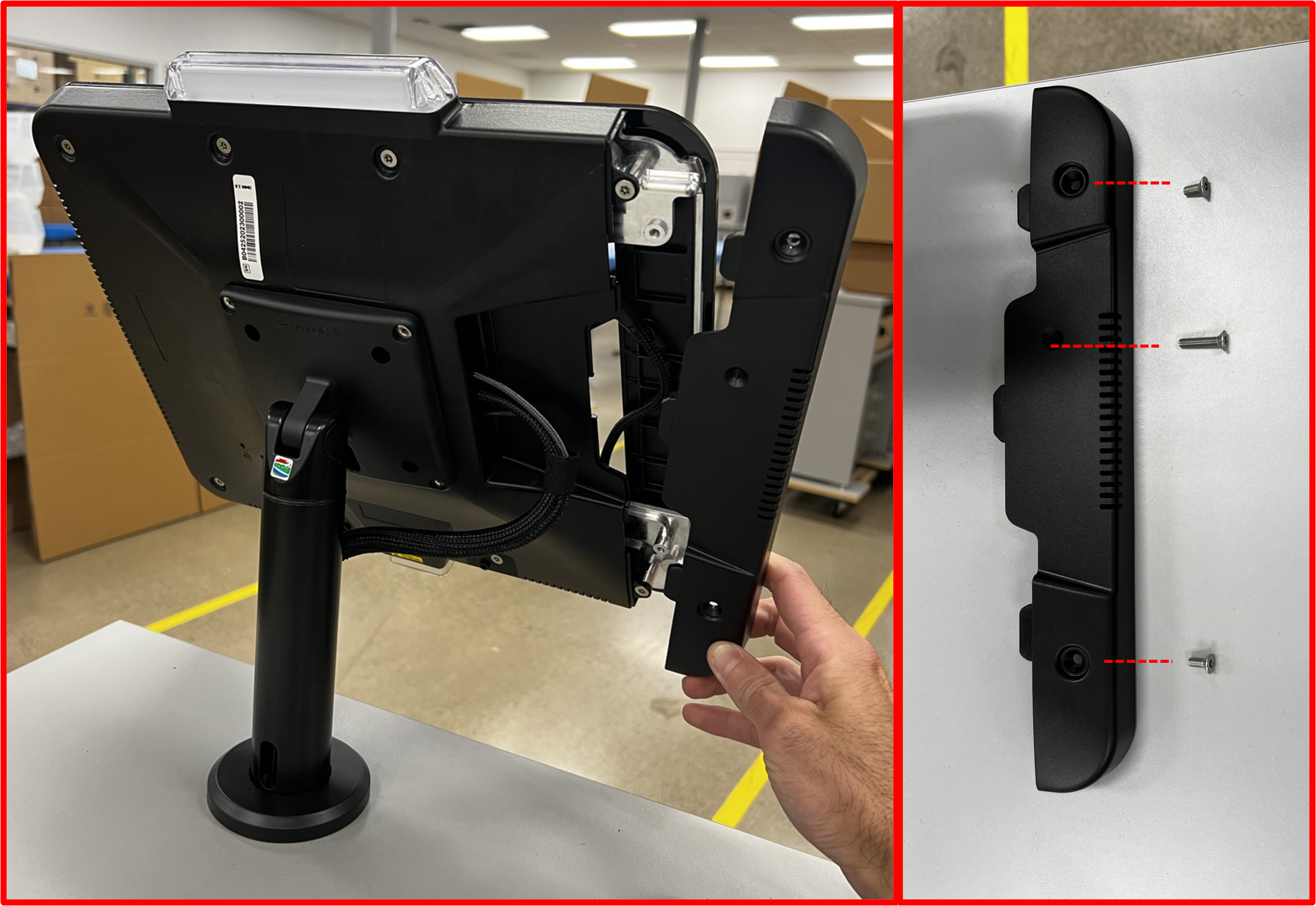
- Slide in
Tablet, taking care to insert with the USB-C end last.
Figure E2.46
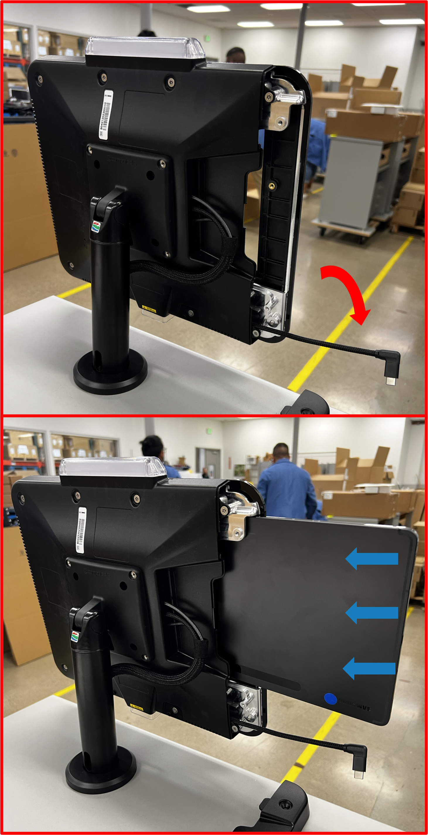
- Slide in
Tabletuntil edge of device is flush with edge ofOMNIdevice.
Figure E2.47
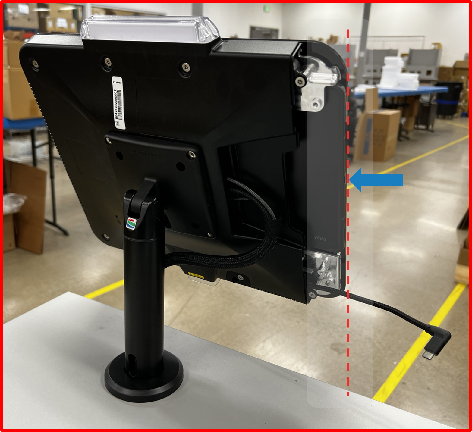
- Connect USB-C cable to
Tablet.
Figure E2.48
ℹ️ NOTE
IfTabletis powered ON at this point, once USB-C cable is connected toTableton-screen pop-ups may begin to appear. Please take care not to cancel or bypass these notifications as these are important to the functionality of the RDS System and application (SEE Step 13 below for proper on-screen interaction and guidance moving forward with application initialization).
- Seat
Tabletfully.
Figure E2.49
- Loop excess cable slack behind
Tabletas shown.
Figure E2.50
- Reinstall
side coverandsecurity screwsto secureTablet.
Figure E2.51
❗ IMPORTANT
For next steps, ensure the following:
Tabletis still powered ON and screen is AWAKE. If screen has turned off for any reason, double tap anywhere on the screen to WAKE/turn ON screen.Tabletis charging. 🔋
Figure E2.52
Step 12 | Install Ethernet Cable (REQUIRED)
- Using supplied
Ethernet cable(included withBOX 1), connect one end to appropriate connection onSUB-SYSTEMlocated in service compartment ofDESK.
Figure E2.53
-
Connect other end to functional LAN network port.
-
Confirm network connectivity of
Tablet.
ℹ️ NOTE
- RDS application should be on a blank white screen at this point if not connected to network. Upon connecting
Ethernet cableand if a proper network connection is establish, RDS application screen should automatically update and appear as shown:
Figure E2.54
- If screen appears blank, close and relaunch the application (SEE Figure 2.39 and Figure 2.40 from Step 10.2 above).
- If screen appears as a blue background, launch RDS application manually (SEE Figure 2.40 from Step 10.2 above).
- Clear any and all error notifications if they pop-up by selecting OK on on-screen prompts (SEE Figure 2.41 from Step 10.2 above).
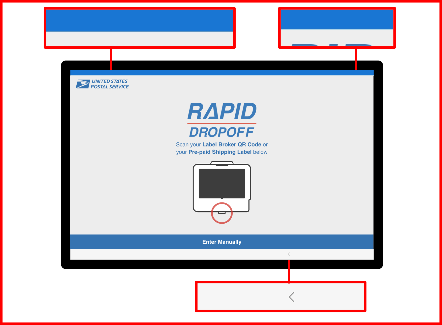
Step 13 | RDS Application Initialization (ON-SCREEN - Tablet)
❗ IMPORTANT
- Before proceeding please ensure the following criteria has been met:
Tabletis secured insideOMNIenclosure. 🔐Tabletis power ON and charging. 🔋Tablethas network connectivity. 📶|🌐
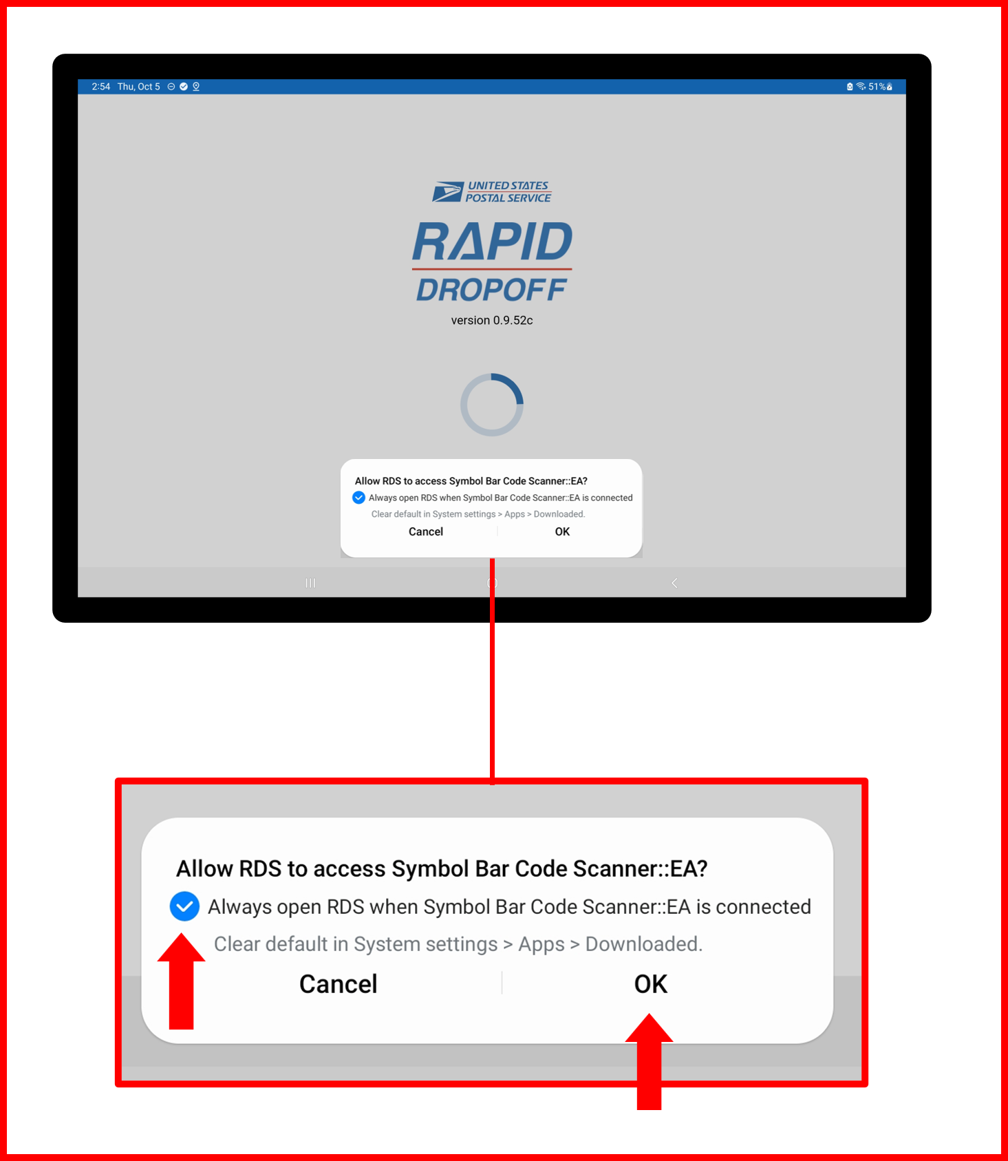
- Accept any and all permissions notification that pop-up. Anywhere from 2-3 notification may be presented.
❗ IMPORTANT
- Be sure to select "Always open RDS when..." option before pressing OK .
Figure E2.55
-
Close and relaunch the application (SEE Figure 2.39 and Figure 2.40 from Step 10.2 above).
-
Again, accept any and all permissions pop-ups same as Step 13.1 above.
-
Again, close and relaunch application same as Step 13.2 above.
ℹ️ NOTE
- Upon application launch this time, no pop-ups (permissions or errors) should occur. If this is the case, then proceed to next steps and continue with application initialization process. ⏭️
- If errors or pop-ups occur, repeat steps 13.3 and 13.4 until there are no more pop-ups to accept. 🔁
- If at anytime during this process the Tablet becomes locked in kiosk mode and closing and relaunching the RDS application is not possible via the above stated method, SEE Supplemental Step C below to disable kiosk mode manually and unlock tablet.
- Enter all the Site Information in available fields on
Provision Devicepage and press Save .
Figure E2.56
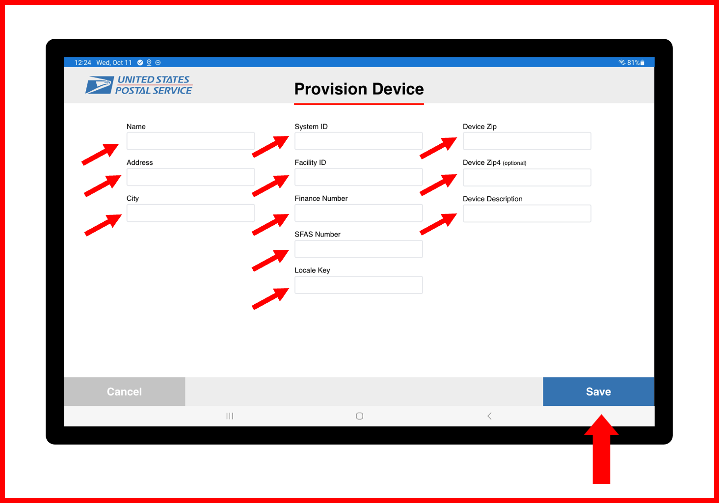
ℹ️ NOTE
IfProvision Devicescreen does not appear on application startup, then Site Information has already been pre-configured. Proceed to next steps to continue application initialization.
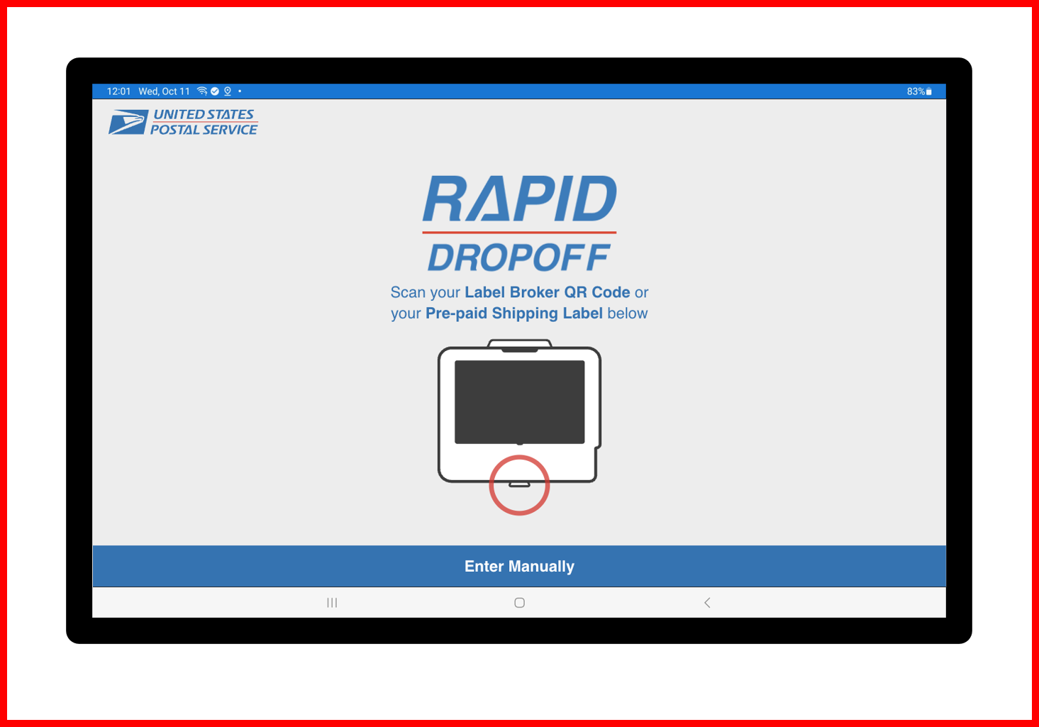
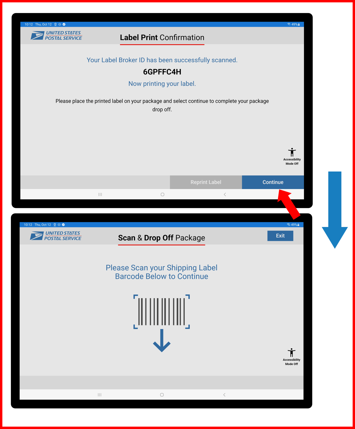
- RDS application should now be initialized and screen should display as shown below:
Figure E2.57
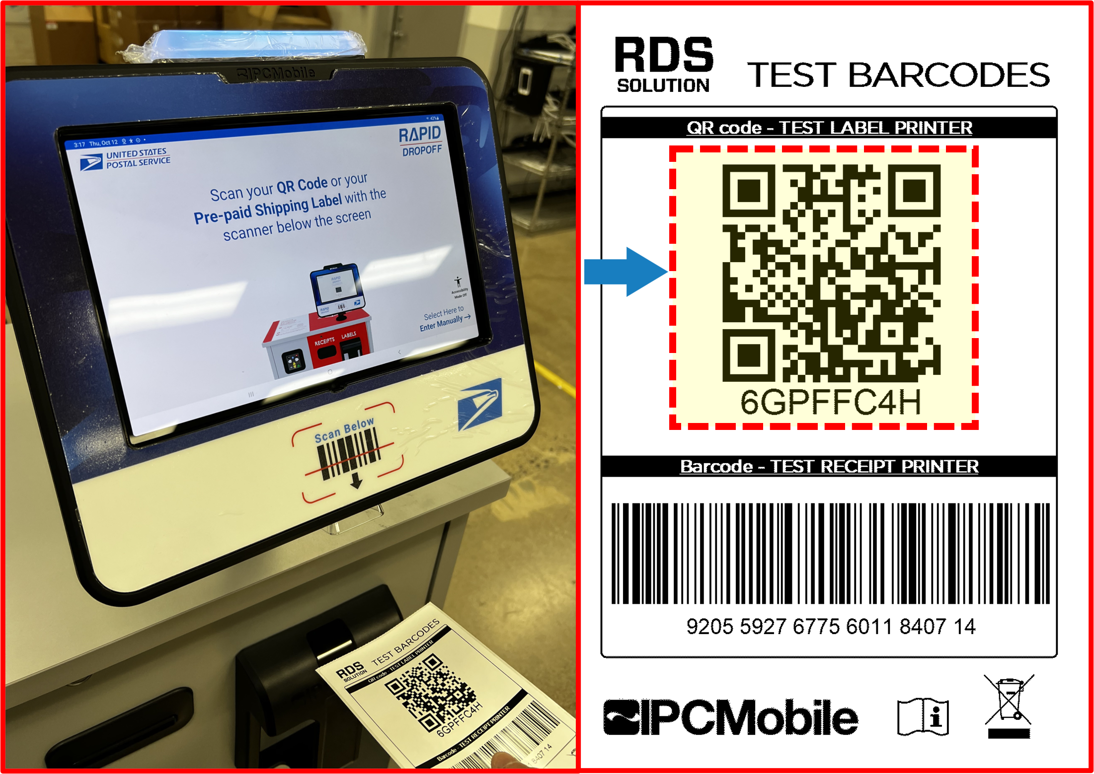
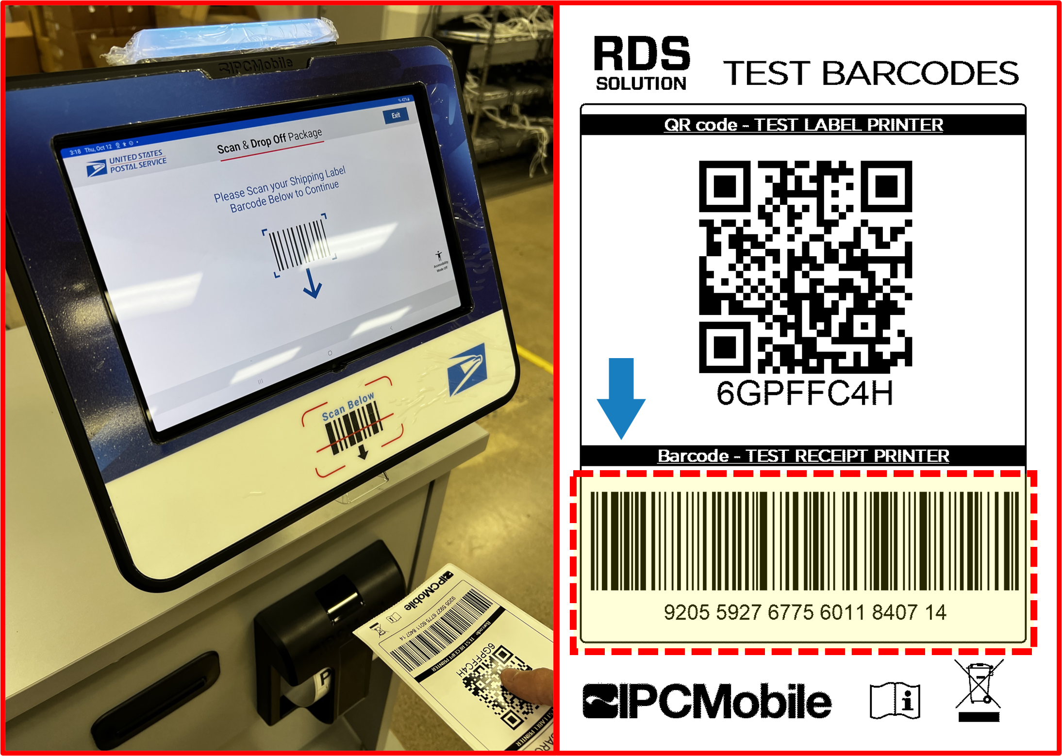
Step 14 | Run Test Transaction Using Test Barcodes
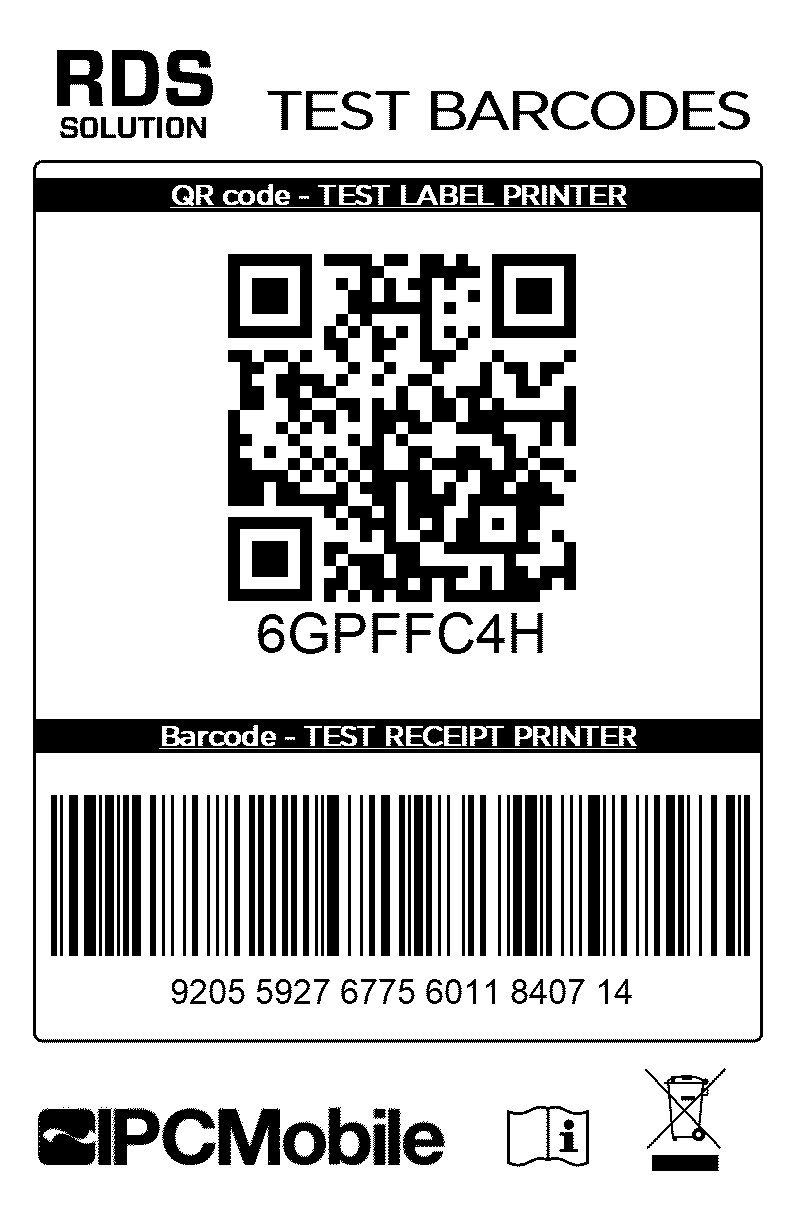
- Using supplied
Test Barcodes Label(found taped to inside of Drawer of Desk), scan QR code to begin Test Transaction.
Figure E2.58
- Follow on-screen prompts (selecting blue buttons ONLY). Be sure to select YES for
Will a 4" x 6" label fit on your package?screen.
Figure E2.59
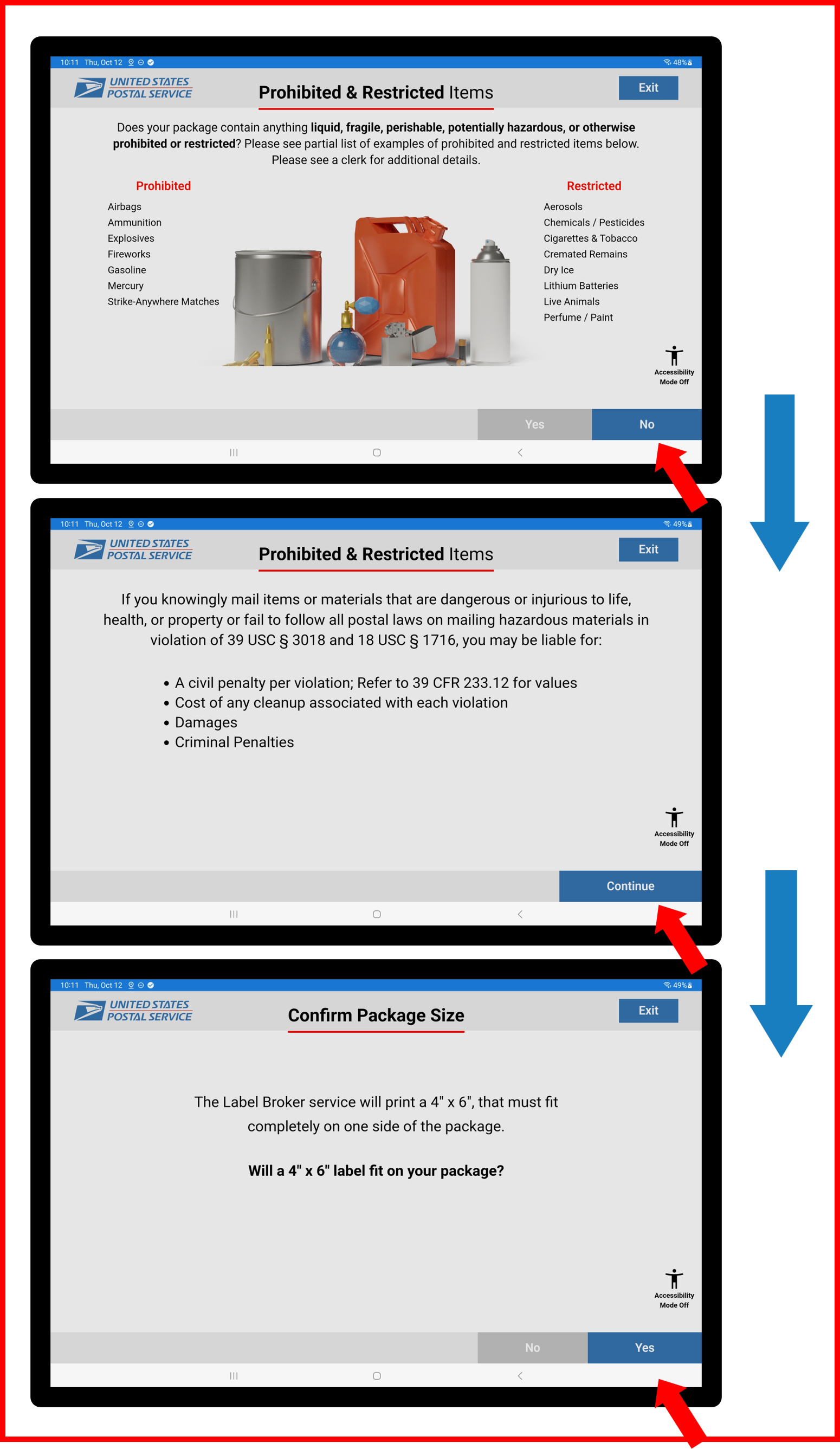
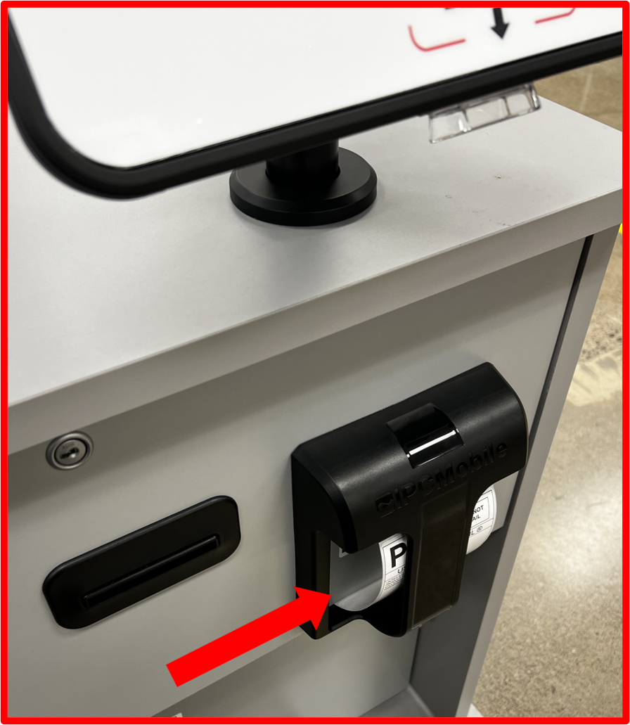
- Test Label should print and eject into Label Catch.
Figure E2.60
ℹ️ NOTE
Confirm Test Label is printed properly and feeds properly into Label Catch area.
- Continue through on-screen prompts (select blue buttons ONLY).
Figure E2.61
- Scan 1D barcode when prompted.
Figure E2.62
- Again, continue through on-screen prompts (selecting blue buttons ONLY). Be sure to select PRINT in
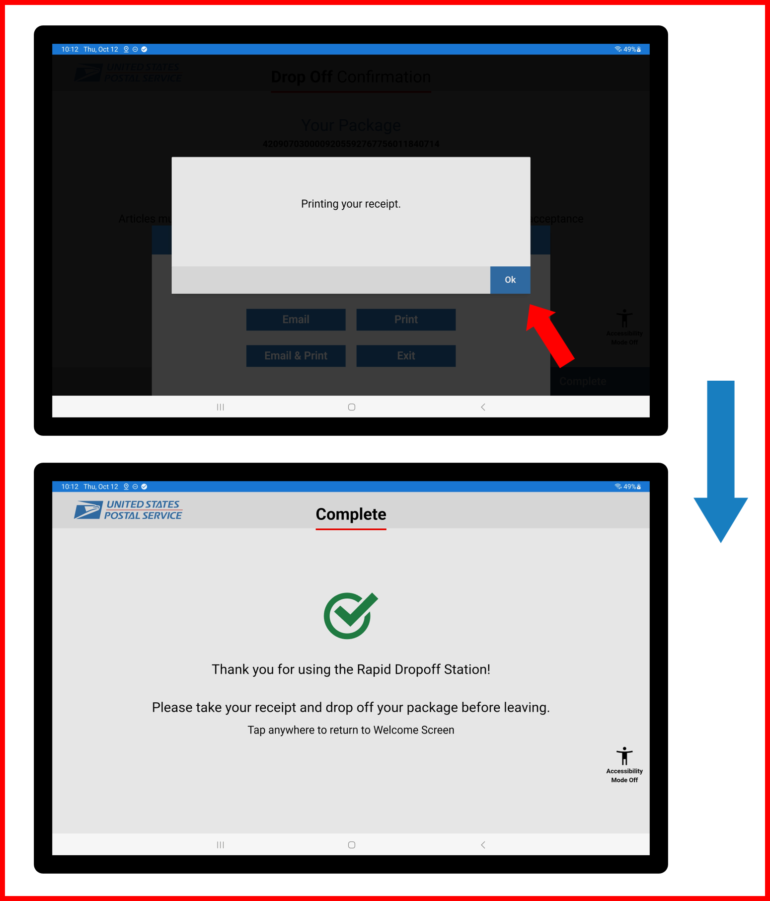
How would you like your receipt?pop-up.
Figure E2.63
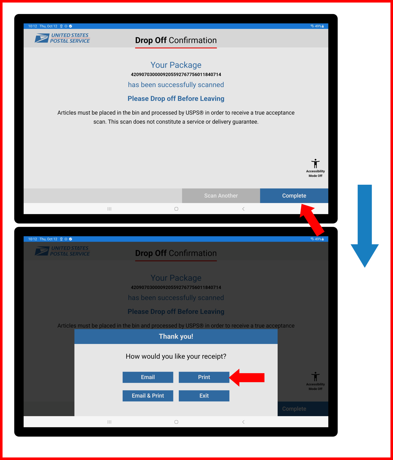
- Receipt should print and feed out of Presenter in center of Drawer. Receipt will remain slightly attached and need to be pulled away.
Figure E2.64
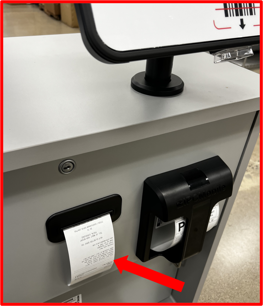
ℹ️ NOTE
Confirm Test Receipt is printed properly and feeds properly through Presenter slot.
- Finalize transaction by continueing through final on-screen prompts (selecting blue buttons ONLY).
Figure E2.65
- Repeat steps 14.1-14.8 three times (3x) through to validate RDS system, application, and printers are functioning properly.
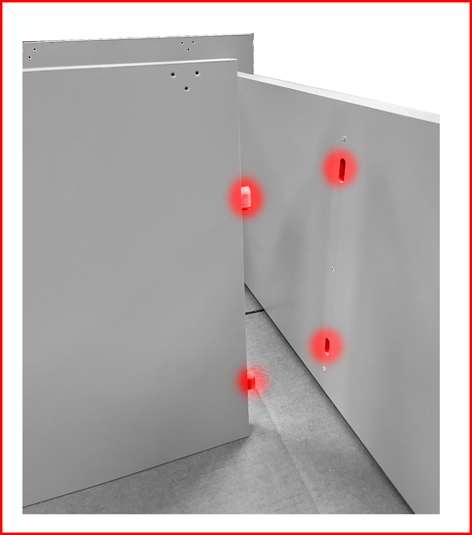
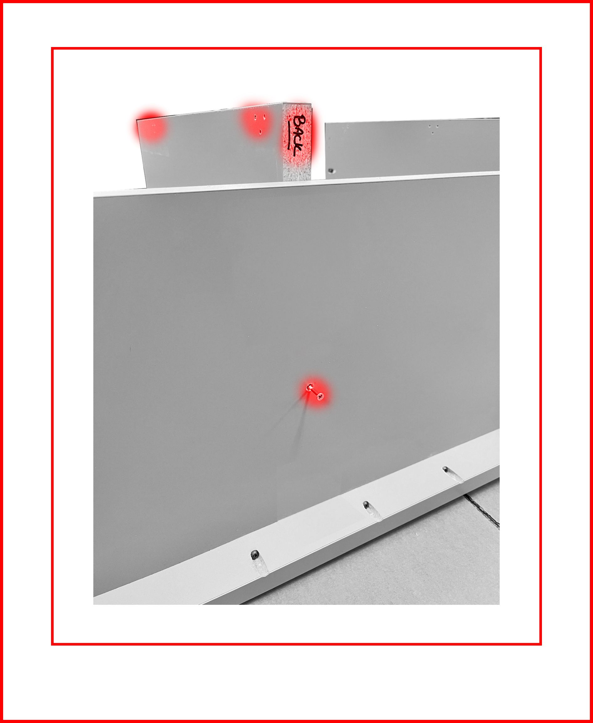
Step 15 | Anchor Desk (REQUIRED)
- Using
Anchoring Kit(BOX 8), install brackets (supplied) ontoDESKusing supplied hardware as shown.
❗ IMPORTANT
- See below images for certified area for mounting anchoring brackets to
DESK.- Recommended drill bit for thru hole:
5/16".- Bracket can be installed in multiple orientations with longer side affixed to
DESK.- Recommend installing brackets in highest mounting position as possible for most secure anchoring.
Figure E2.66
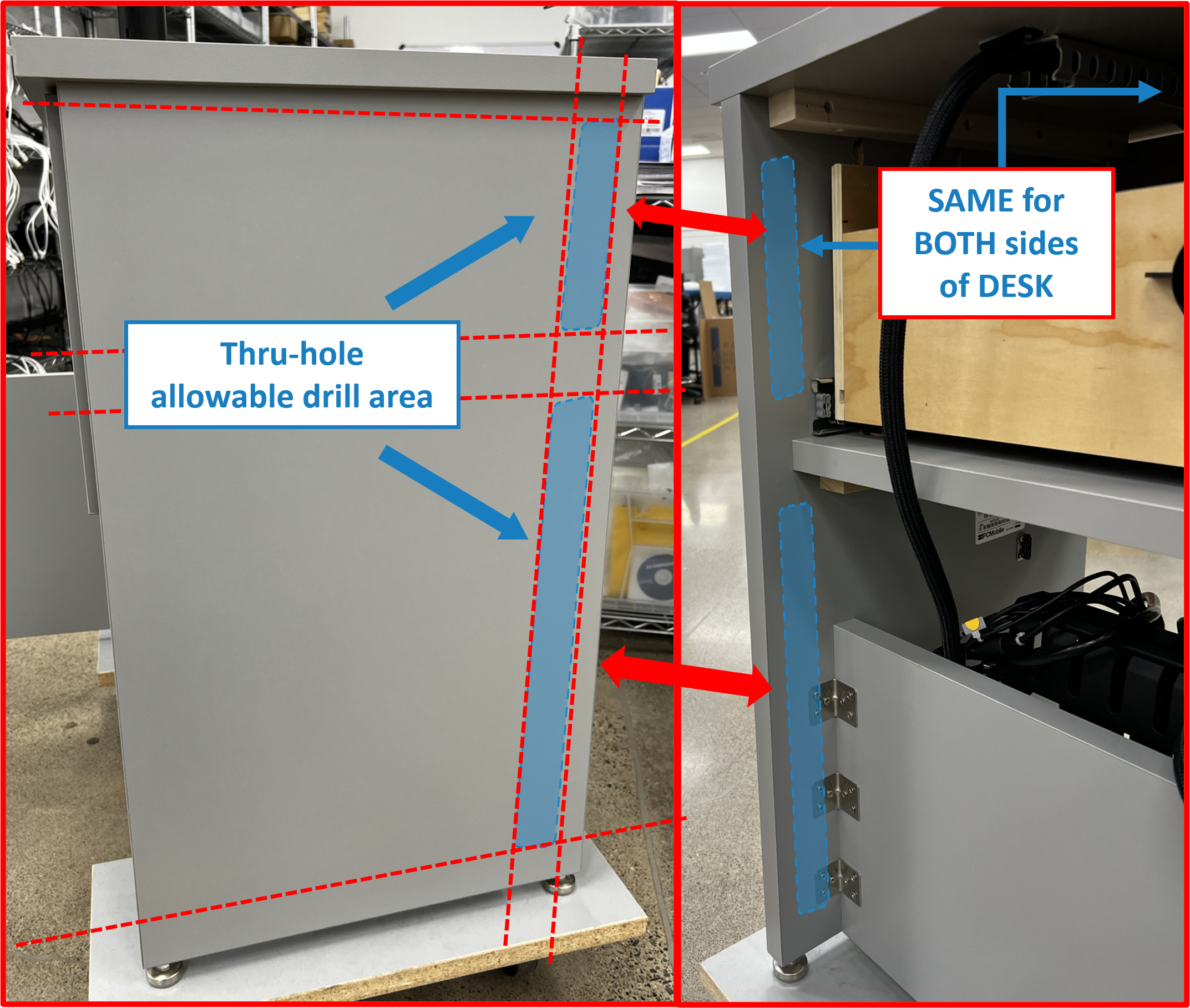
Figure E2.67
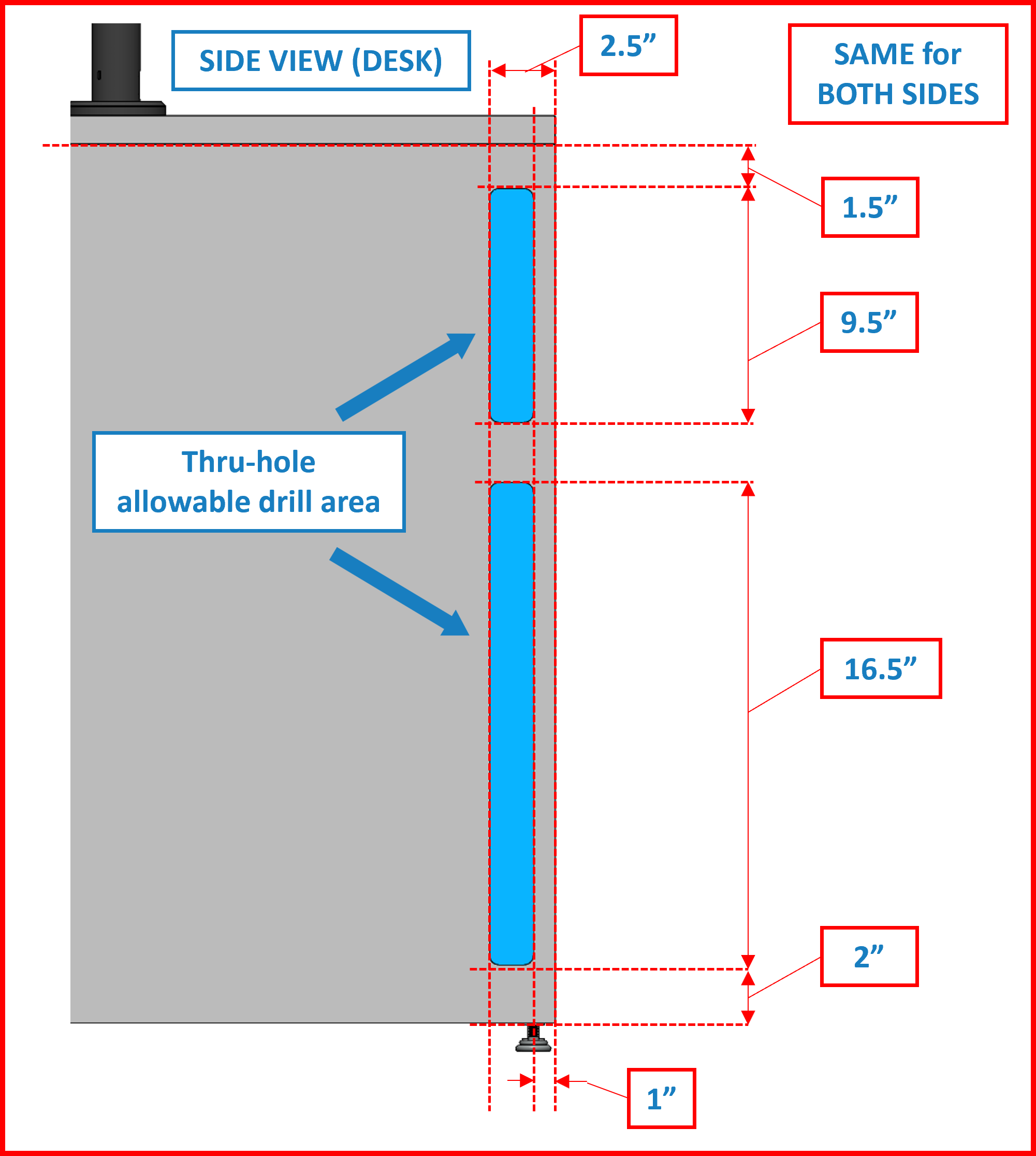
Figure E2.68
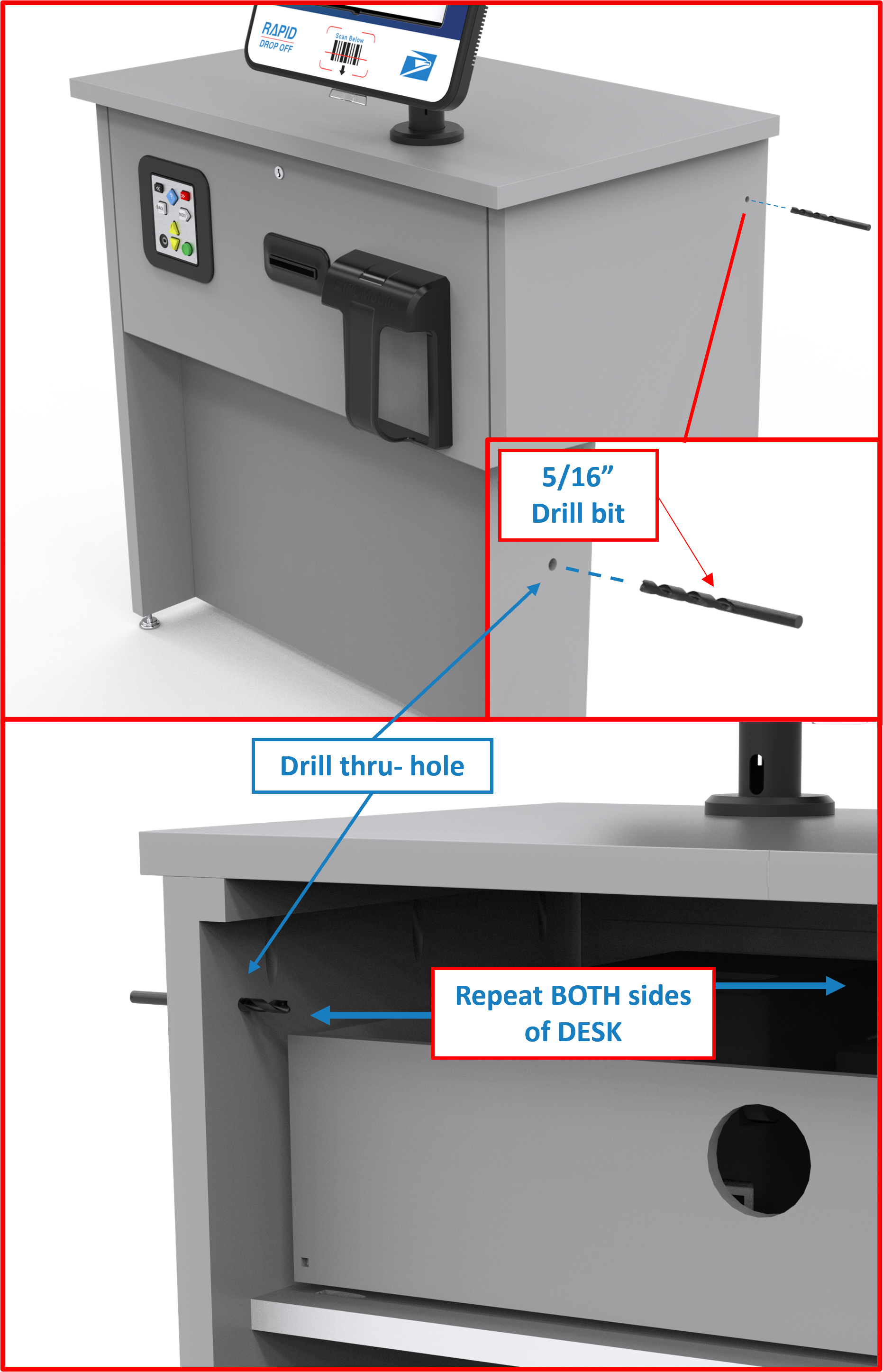
Figure E2.69
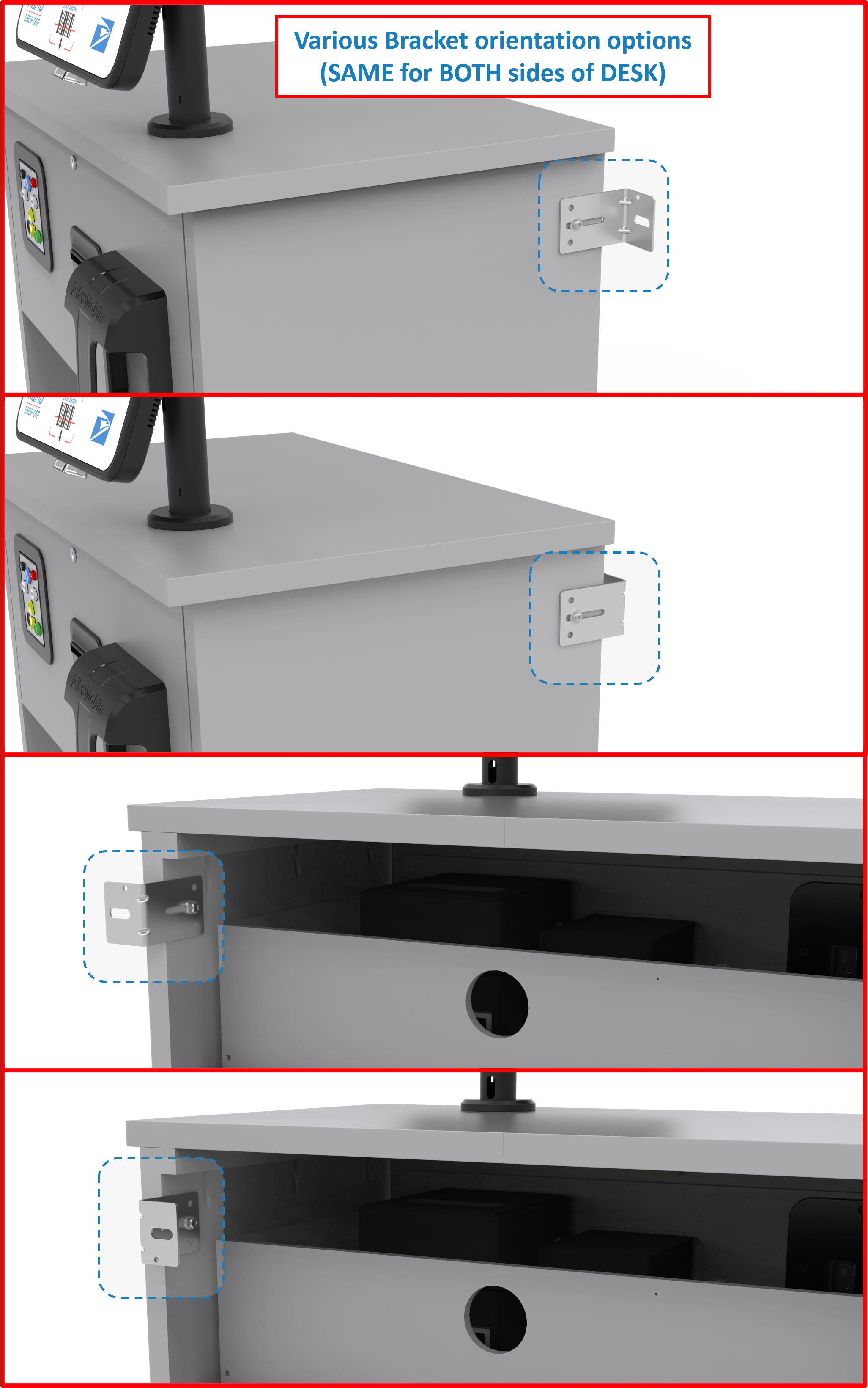
Figure E2.70
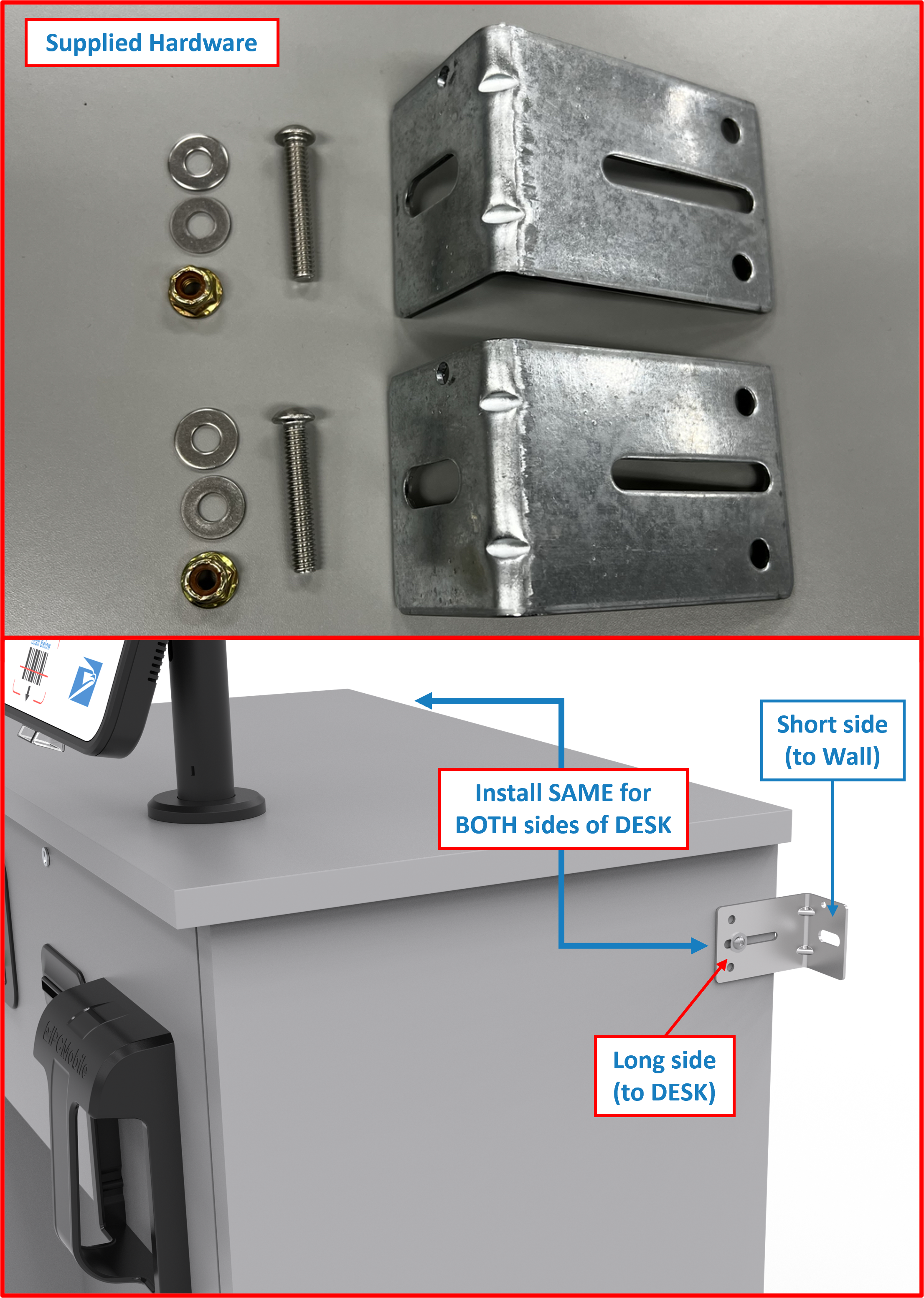
- Anchor to wall using appropriate hardware and installation method.
ℹ️ NOTE
Wall mounting hardware NOT supplied.
⚠️ WARNING
AnchoringDESKsecurely to wall or secure fixture is REQUIRED for safety.
Supplemental Steps ➕
ℹ️ NOTE
Below steps are supplemental steps that may or may not be required during the setup and installation process of RDS. If NOT needed, skip to ⏭️ FINAL STEPS.
Supplemental Step A | Powering ON Tablet within OMNI
ℹ️ NOTE
Powering ON theTabletvia this method is required if theTabletbattery has died or Tablet has shutdown for any reason. Please refer to Steps below ifTabletscreen is blank (BLACK) and will not respond to double tapping screen to WAKE/turn ON.
-
Using supplied
PIN TOOL(BOX 7), insert long end into opening markedOon backside ofOMNI. -
Press-in
PIN TOOLfirmly and hold for 5 seconds. Samsung splash screen should appear to signifyTabletis booting up.
Figure 3.1
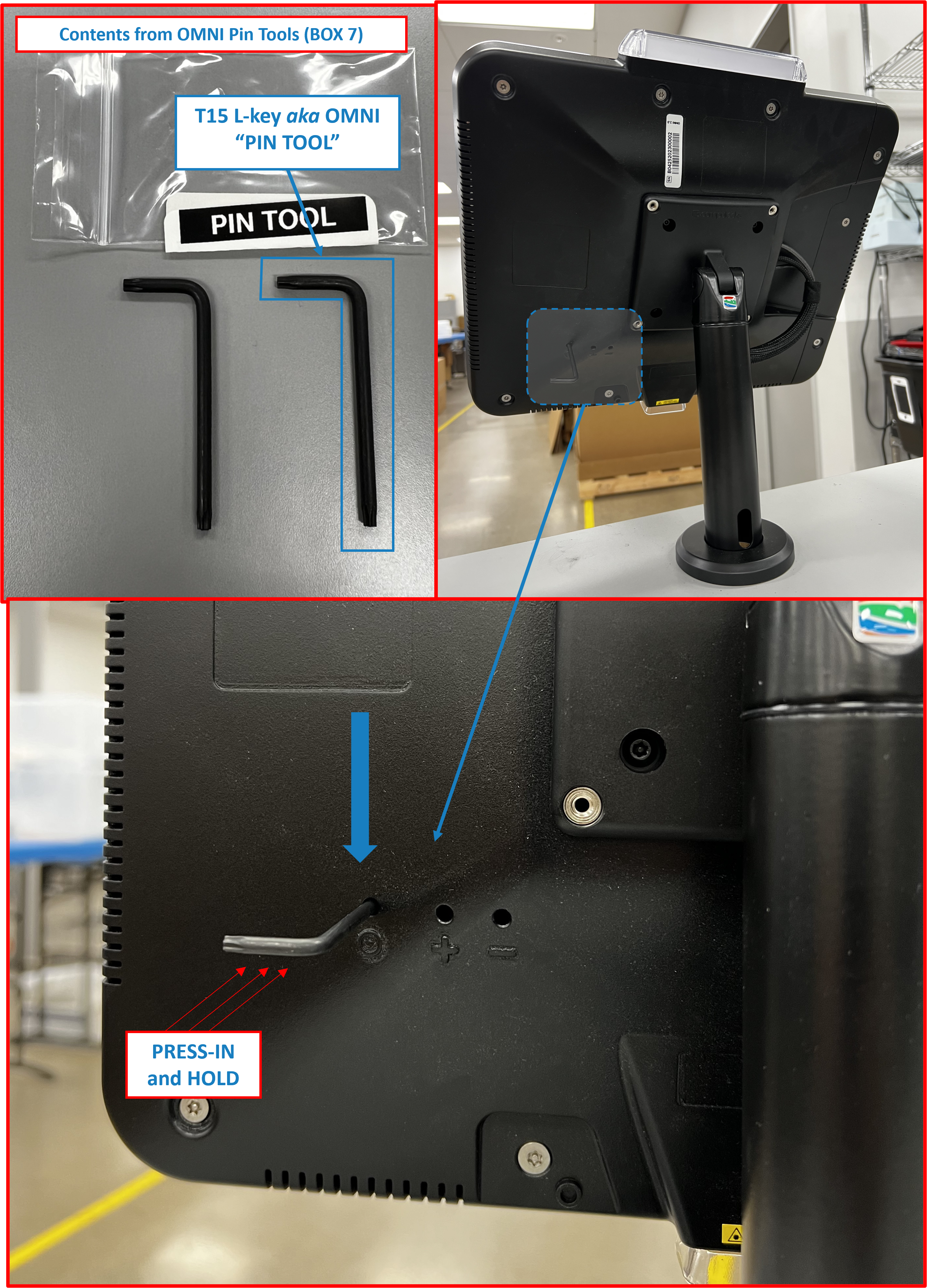
ℹ️ NOTE
Samsung splash screen will appear upside down at this point. This is NORMAL.Tabletscreen orientation will rotate and correct itself upon boot up.
Figure 3.2
Supplemental Step B | Resetting Tablet within OMNI - HARD RESET
ℹ️ NOTE
ResettingTabletvia this method is required if the Tablet is ON but application has become unresponsive and there is no way to exit kiosk mode or reset the application. Please refer to below steps if Tablet screen is blank (WHITE) and/or frozen and locked in kiosk mode.
-
Using both supplied
PIN TOOLS(BOX 7), insert long ends into opening markedOand-on backside ofOMNI. -
Press-in both
PIN TOOLSfirmly and hold for at least 12 seconds.Tabletscreen should turn OFF. At this point release pressure on thePIN TOOLS.
Figure 3.3
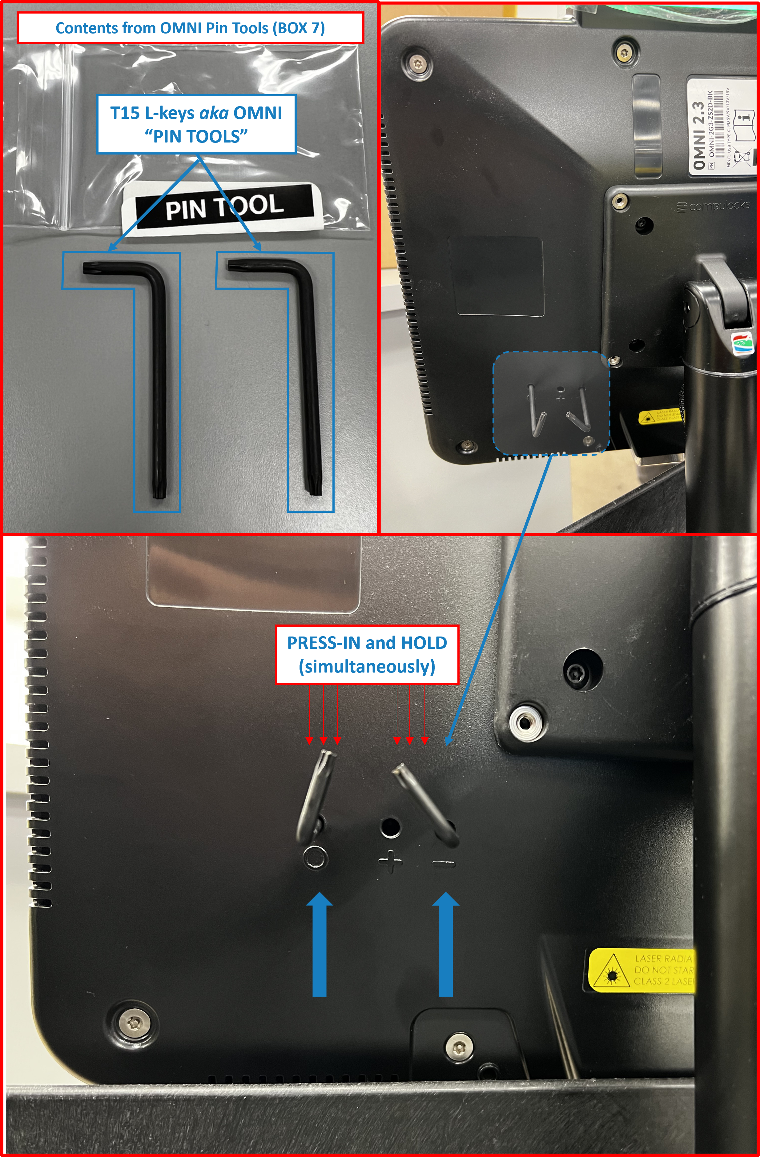
- Tablet screen will remain blank for a few seconds, followed shortly by Samsung splash screen appearring to signify
Tabletis re-booting.
ℹ️ NOTE
Samsung splash screen will appear upside down at this point. This is NORMAL.Tabletscreen orientation will rotate and correct itself upon boot up.
Figure 3.4
Tablet may restart itself repeatedly. Please be patient as this may take 1-2 minutes to fully reboot. RDS application should relaunch automatically after reboot.
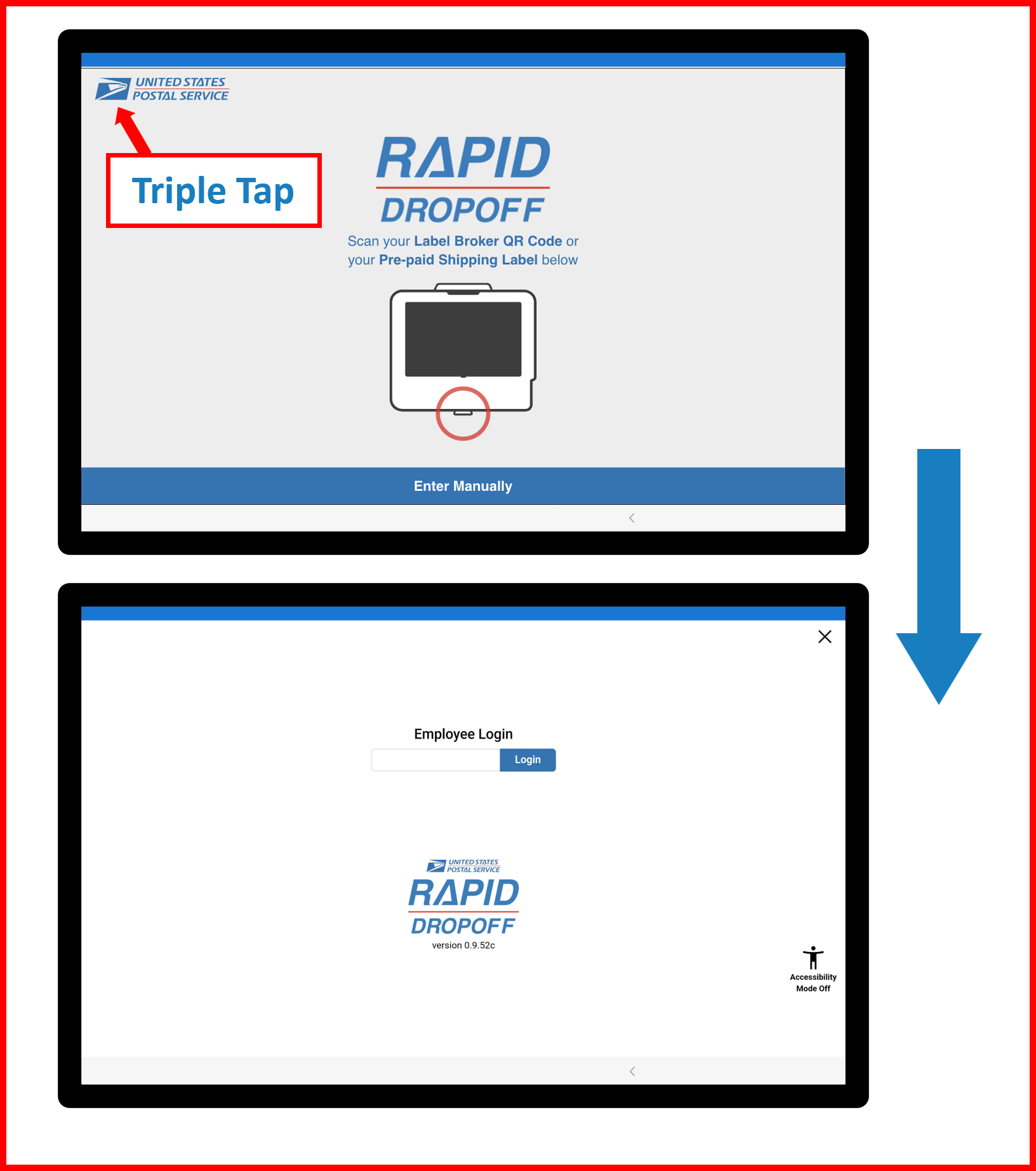
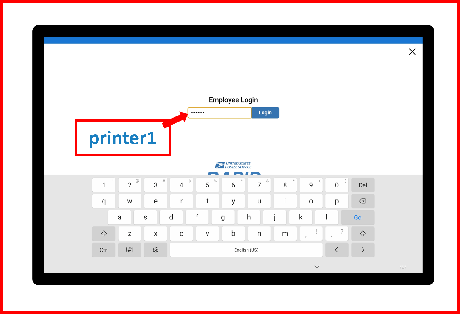
Supplemental Step C | Disabling Kiosk Mode - Manual Method
ℹ️ NOTE
Use below method to disable Kiosk Mode if needed during application intialization process.
Kiosk Mode
enabled- on-screen indication:Figure 3.5
- Triple tap (3X) USPS logo in upper left corner of RDS application Home Screen.
Figure 3.6
- Enter
printer1in Employee Login Field.
Figure 3.7
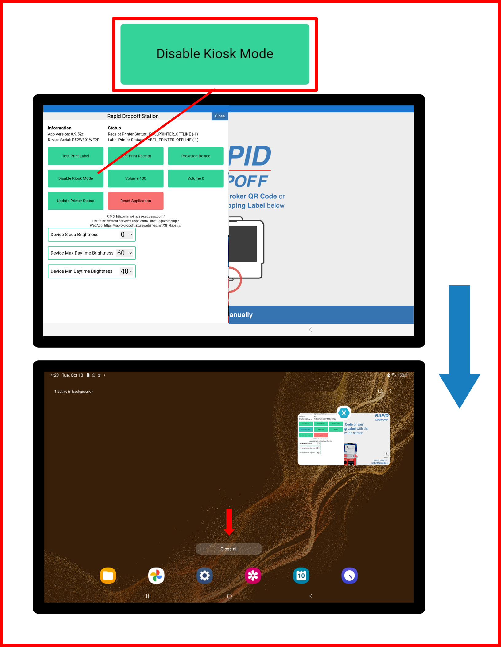
-
Select
Disable Kiosk Modebutton. -
Select
Close allbutton to close RDS application.
Figure 3.8
- Relaunch RDS application.
Figure 3.9
- RDS application should startup with Kiosk Mode
disabled.
Installation portion of RDS Solution is now complete. 🏁
FINAL STEPS ⤵️
❗ IMPORTANT
- Contact USPS RDS Support Team BEFORE LEAVING THE SITE to complete final steps to bring the system online and complete remote setup. ✔️|🔐
QUICK LINKS ⤴️
- To TOP of Table of Contents 🔝
- To TOP of Unboxing Section 🔝
- To TOP of Installation Section 🔝
- To Troubleshooting Guide ⏭️
- To Changelog Δ 🪵