
RDS Troubleshooting Guide
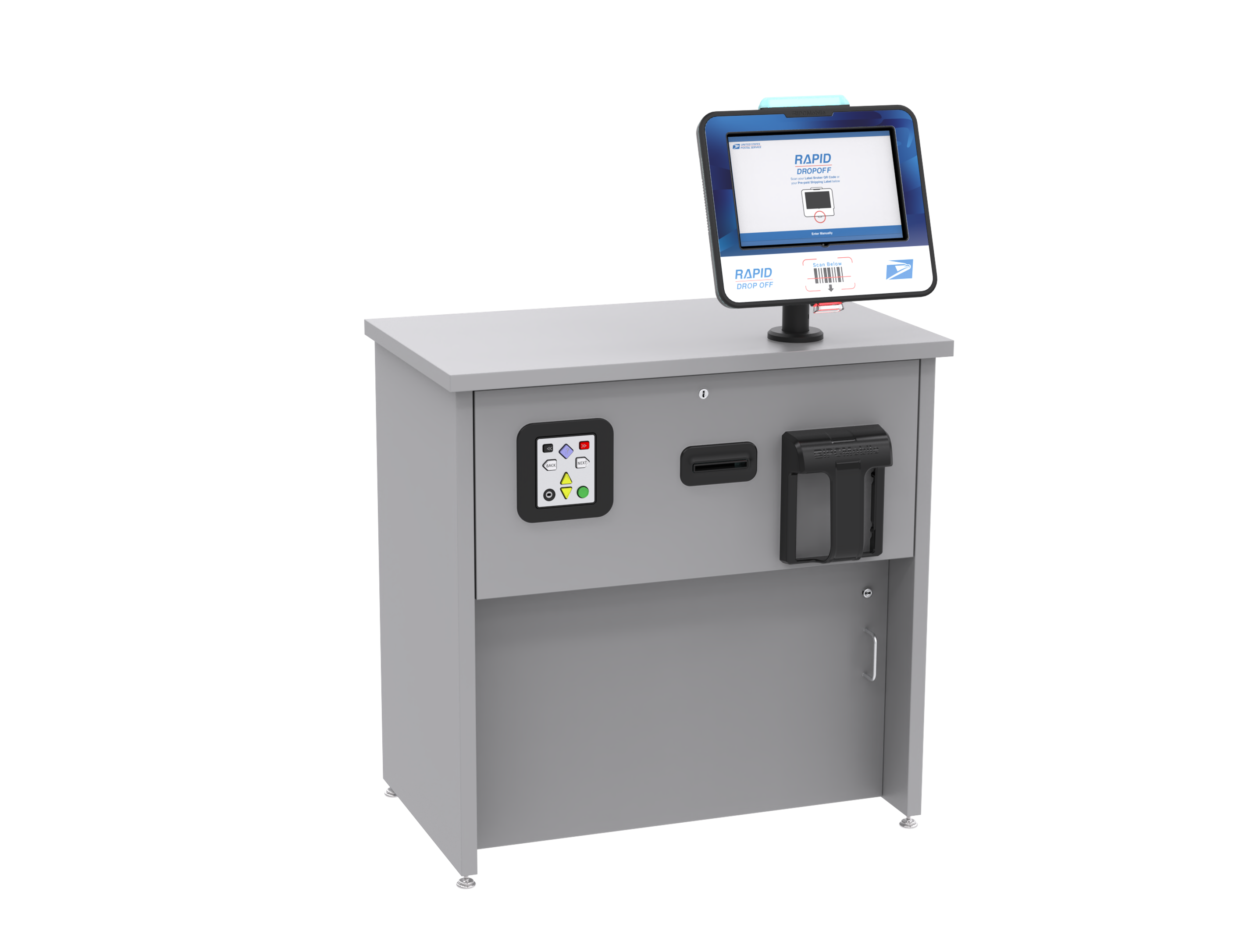
Table of Contents 📝
Replacing OMNI and Pole Mount
Required Tools and Parts
Figure TS.A1
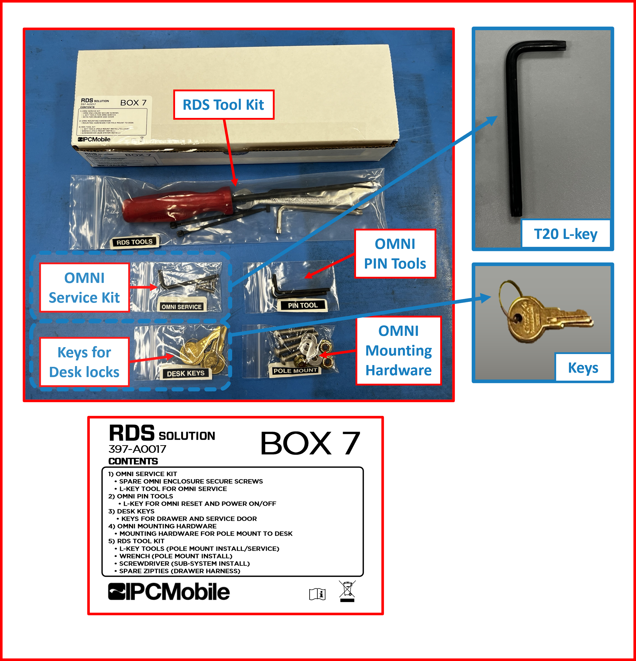
Figure TS.A2

Links 🔗
- Video to remove OMNI and POLE MOUNT
- Removing OMNI and POLE MOUNT instructions.
- Installation of OMNI and POLE MOUNT instructions.
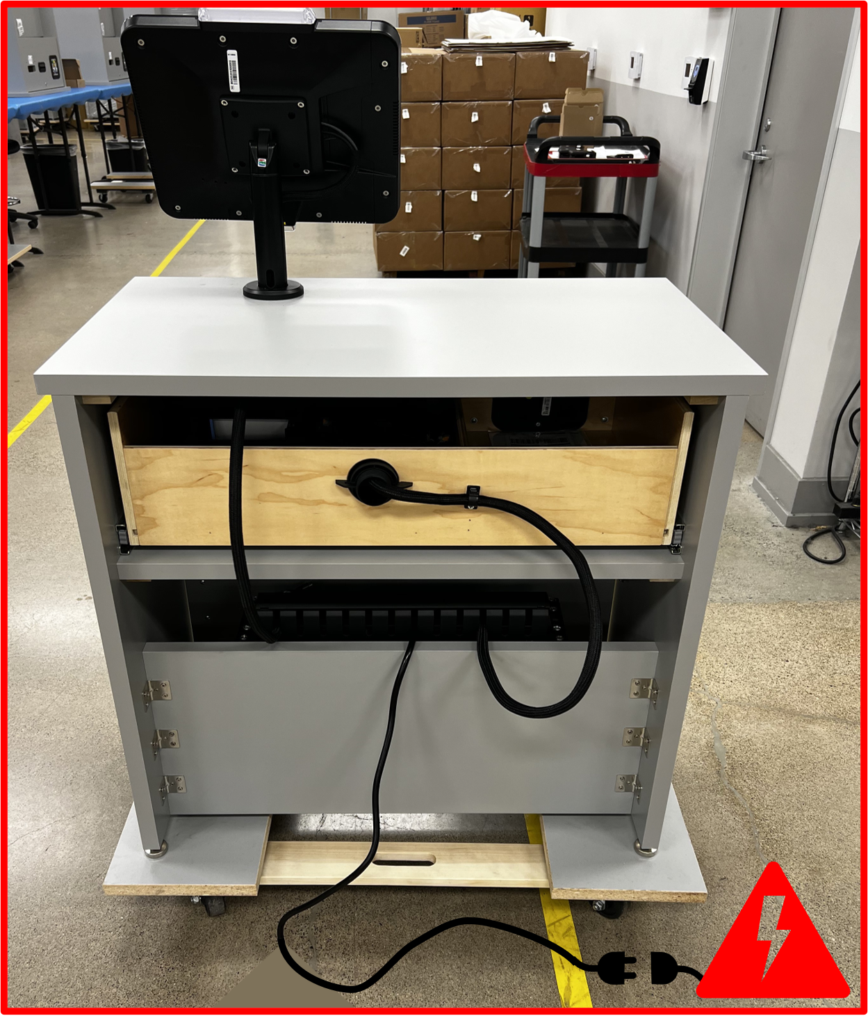
Accessing Cables and Power Down the System
- Use the necessary tools as to de-anchor the
Deskas to permit access to the back of theDeskand to power socket.
Figure TS.A3
- Unplug the RDS system from the main power source.
Figure TS.A4
- Access the service door with provided key. Accessing the service door permits access to the hub and cables to disconnected.
Figure TS.A5

- Identify the
USB-C hub.
Figure TS.A6
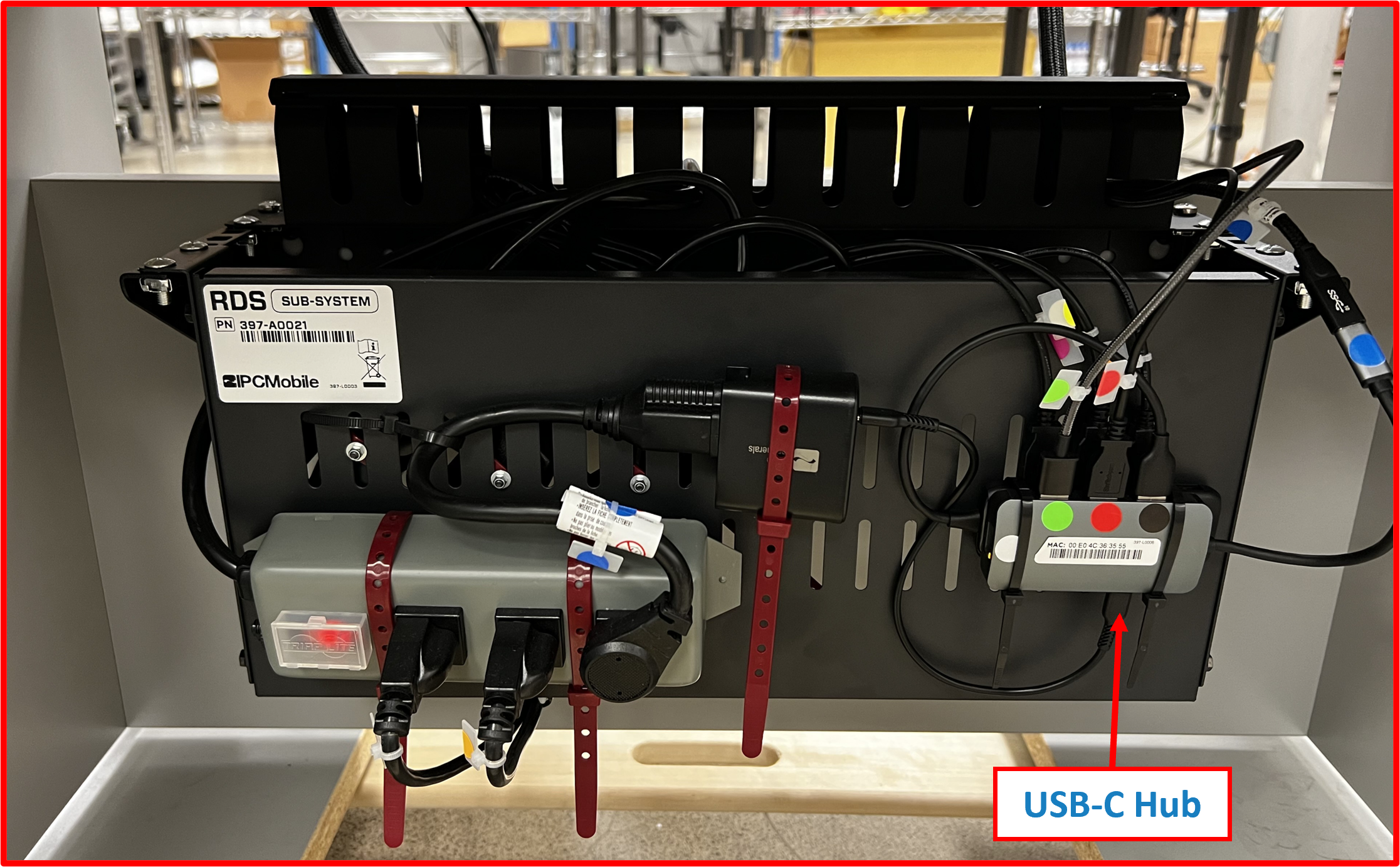
-
Unplug the following cables from the port:
a) LED cable designated as the GREEN dot 🟢.
b) Scanner cable designated as RED dot 🔴.
c) Tablet cable designated as BLACK dot ⚫. -
These 3 cables make the
OMNI harness. -
Lift the
coveroff thebracket.
Figure TS.A7
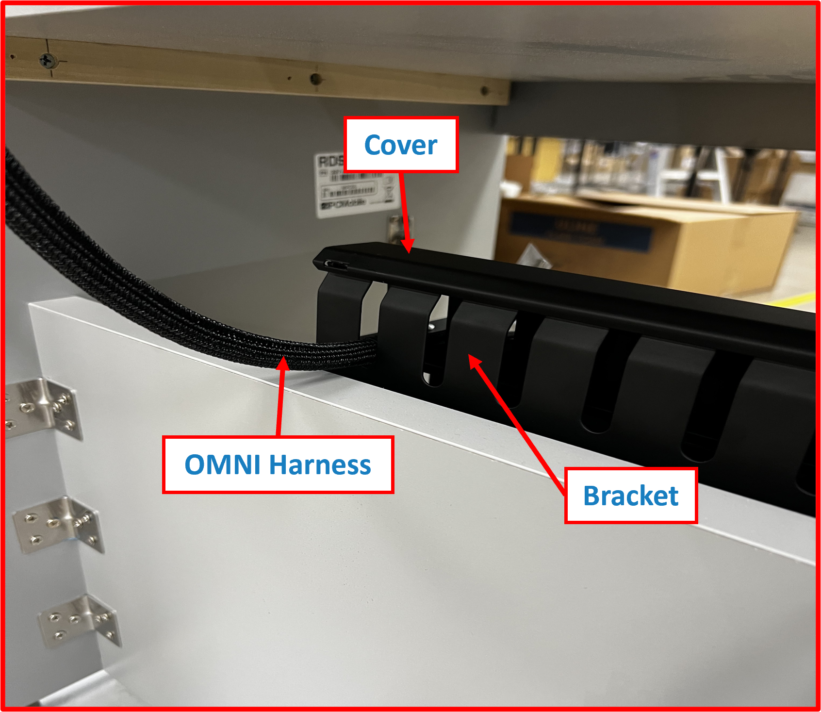
Figure TS.A8
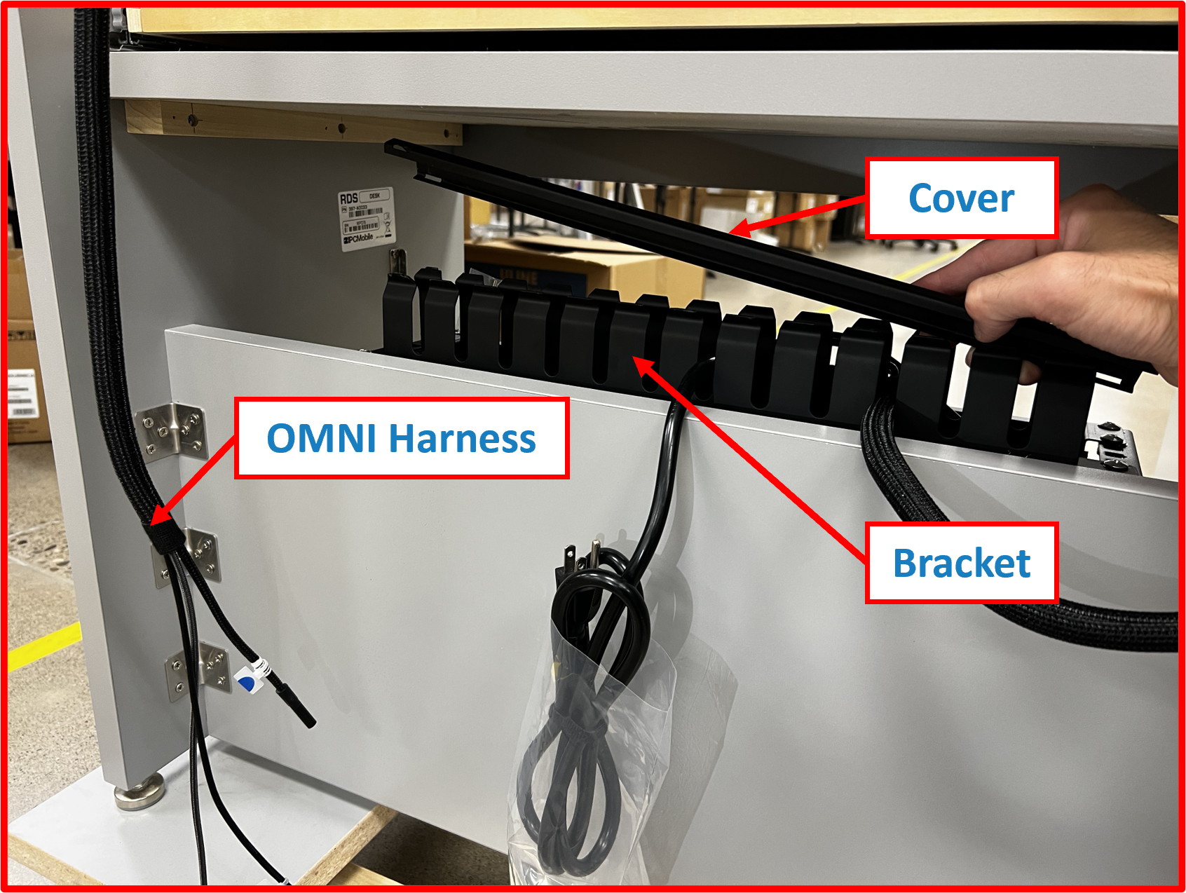
-
Remove the
OMNI Harnessas to not unplug any other ports during process. -
Release the
OMNI Harnessfrom thecable duct.
Figure TS.A9

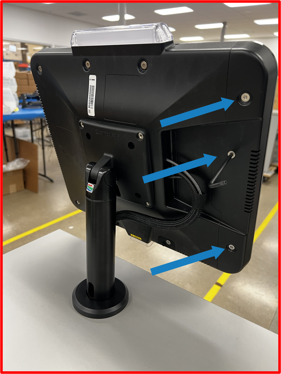
OMNI Tablet removal
- Obtain the T20 L-Key that was provided with initial installation kit.
Figure TS.A10

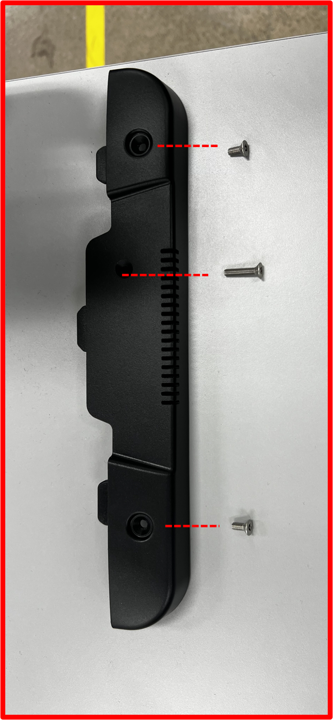
- Identify the 3 screws on the back of the Omni.
Figure TS.A11
- Unscrew the screws and secure the screws.
Figure TS.A12
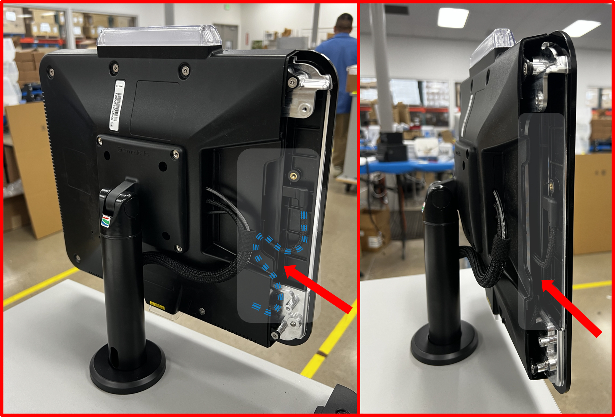
- Side cover can now be separated from the main housing, and the tablet and USB C cable shall be exposed.
Figure TS.A13

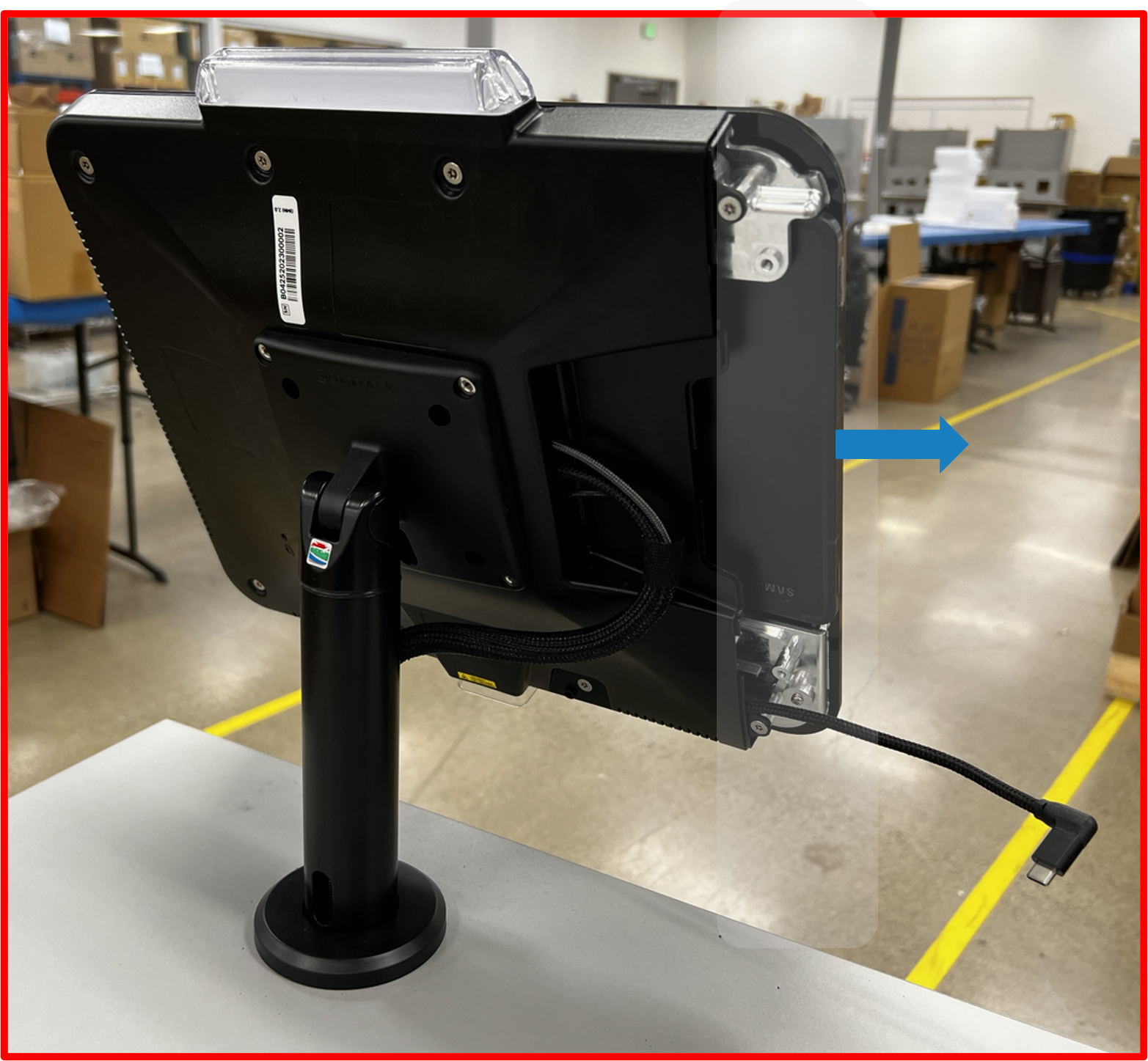
- Disconnect the USB C cable from the tablet.
Figure TS.A14
- Slide the tablet out and safely secure the tablet from theft and damage.
Figure TS.A15
OMNI and POLE Mount removal
-
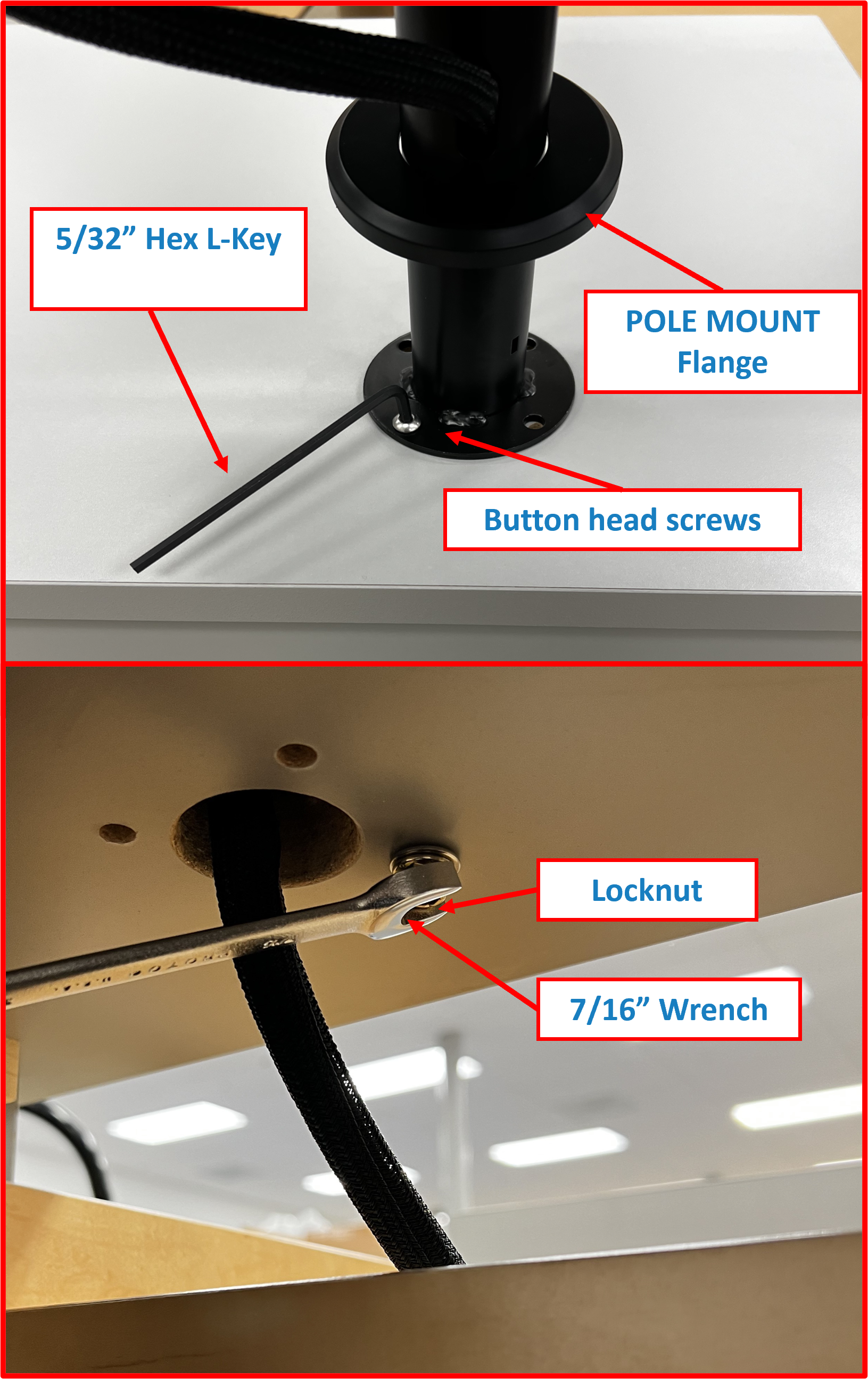
To unmount the
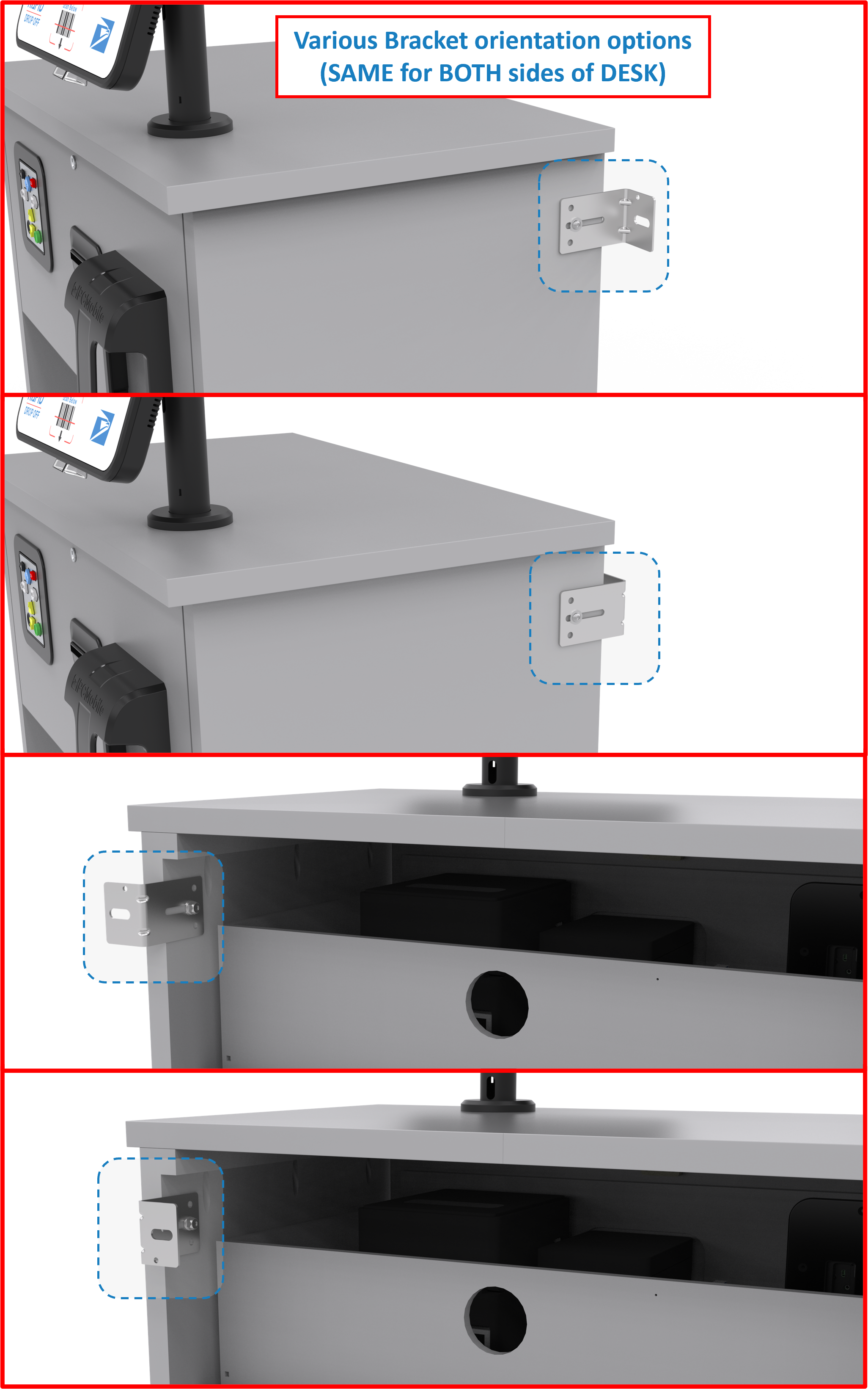
OMNIand thePOLE MOUNTfrom theDesk, obtain a5/32” Hex L-Keyand7/16” wrench. Tools should be available from prior installation and or kit was provided for removal. -
Lift the POLE MOUNT
flangeas to expose the hex button head screws and engage the5/32” Hex L-Key. In addition, using the7/16” wrench, engage the locknut. In turn, unscrew the button head screw. -
Repeat steps 1 and 2, for each screw and nut that retains the POLE MOUNT.
Figure TS.A16
ℹ️ NOTE Take caution after the last screw is removed as to not let the OMNI and POLE MOUNT fall off the desk.
- Lay the
OMNIandPOLE MOUNTon theDeskand theOMNI HARNESScan now be extracted taking care that theOMNI HARNESSdoes not get caught on other wires.
Figure TS.A17

-
Extraction is now complete and the new
OMNIandPOLE MOUNTcan be installed. -
See the following installation guide and setup requirements to install the new unit starting at Step 1 | Install OMNI + POLE MOUNT Assembly onto DESK.
QUICK LINKS ⤴️
- To TOP of Table of Contents 🔝
- To TOP of Replacing OMNI and Pole Mount 🔝
- Back to RDS Setup Guide 🔙
- To Changelog Δ 🪵